- Posts: 33
- Thank you received: 0

ACMOC Membership Benefits
- FREE quarterly magazine filled with content about antique Caterpillar machines
- FREE classified listings
- ACMOC store discounts and specials
- Full Bulletin Board Access
- Marketplace (For Sale/Wanted)
- Technical Library
- Post attachments
$44 /year ELECTRONIC
$60 /year USA
$77 /year International
Hello Guys!
- Grader Dude
-
 Topic Author
- Offline
- Junior Boarder
- User
Less
More
13 years 2 months ago #62807
by Grader Dude
Replied by Grader Dude on topic Hello Guys!
I know for a fact you know more about these things then I do, that is why I have come here to seek yours and others advise, I really do love this stuff and would love to soak up all the knowledge you have to offer me, especially stories!
Please Log in or Create an account to join the conversation.
- Deas Plant.
-
- Offline
- Platinum Boarder
- User
Less
More
- Posts: 6637
- Thank you received: 928
13 years 2 months ago #62822
by Deas Plant.
You have a wonderful day. Best wishes. Deas Plant.
Replied by Deas Plant. on topic Cop This!
Hi, Folks.
Cop this!
Adjustment instructions for pre-hydraulic Caterpillar gear-controlled graders.
Here are the 'destructions' for adjusting blade lift controls on older Cat gear-controlled graders.
Firstly, for those looking to achieve a quick fix for worn dog clutches in the control box itself, there AIN'T one. If you want to restore your dog clutches to like-new condition, you need to do one of two things:
a. Buy new ones - 100% reliable.
b. Have them rebuilt and ground back to NEW specs - less reliable as you need first to get hold of the technical data relating to correct pitches, etc., then find an engineering shop that can do it properly.
Some people try grinding them back with an angle grinder. This MAY(????) make an improvement but will NOT return them to new condition.
You can also do a switch-around of the dog clutches in the control box so that you end up with less worn clutches on the blade lift control shafts. This DOES take a bit of brain work as you MUST keep correct track of which clutches are turning which way to do whatever it is that they do so that you do get the less worn faces doing the work.
The output shafts from the control box, are held (more or less, depending on wear) firmly in place when the control lever is released by the "combination shifter fork and brake", which is inside the power control box (the big housing in front of your knees when sitting in the seat that has all the control levers attached to it).
There are two brake plates, which are contained within the shifter fork itself, and a HEAP of small coil springs that push these two brake plates apart when the control lever returns to the released position. This holds the control output shaft in a "braked" position, when the control lever isn't being pushed or pulled.
For some strange reason(????), these brake plates wear after a lot work and/or the coil springs weaken, causing the braking action to weaken allowing the control shafts to turn when load is applied to the other end of the drive-line. All the control levers and drive shafts use the same "combination shifter fork and brake", so you may be able to swap the various shifter fork and brake mechanisms to other positions, and replace the more used and worn ones with less-worn ones, as a "quick fix". Failing that, you will need to dismantle the shifter fork and brake mechanism and replace the springs and possibly the brake plates, with better, or new ones.
I have never seen a 70D Cat 12E as they were American-built. We had the 17K DowNunder which was the DowNunder-built equivalent of the 70D/71D while the earlier 99E was the U.S. equivalent of the DowNunder 21F Cat 12E The later 21F/99E machines and the 17K/70D machines had a small brake arrangement on the front of the blade lift output shaft in front of the control box. It IS possible to have this brake adjusted too tight. So long as the linings are in reasonable condition, these brakes gave very little trouble, at least in my experience.
First step for the rest of the adjustments - remove the inspection plugs on top of each Hi-lift gear case - the big round cases on each side of the front face of the cab. Then loosen the clamp bolts on the lift arms at the front ends of the lift shafts and remove the keys from the blade lift arms. Now slowly rotate the hi-lift gear inspecting it as it turns to find the least worn section which will be around 1/3 of its total circumference. When you have found the least worn section, which should be at the top if you are looking at that section, mark the top of the lift shaft and turn that mark to the bottom. This should leave you with a keyway facing pretty much horizontally outward ready to accept the lift arm key again.
When the mark is at the bottom, replace the key in the lift arm in the nearest keyway that lines up - there should be 3 keyways in the shaft - tighten the clamp bolts and replace the inspection plug in the top of the gear case.
Second step - locate the blade lift pinion at the bottom of the Hi-lift gear case - it is the smaller round part of the Hi-lift gear case running across the bottom of the main case. In most models of Cat grader with the gear lift system, there is a large adjusting screw in the outboard end of the pinion gear case. This adjusting screw has a lock nut on it. With the blade lifted SLIGHTLY, loosen the locking nut and turn the adjusting screw in until it starts to become firm - NOT DEAD TIGHT - and re-tighten the locking nut making sure that the adjusting screw DOES NOT turn as you tighten the lock nut.
When you have the lock nut tightened, it is a good idea to start the machine and test the controls as tightening the lock nut can change the adjustment on the screw even though the screw may not have moved during the tightening. If this happens, it is usually due to worn threads. A bit of fiddling may be required to achieve the best adjustment
(I found that a home-made wrench made from 1 1/2” x ¼” flat bar bent in an 'L' shape with the leg of the 'L' only about 1” long and made to fit the slot in the adjusting screw was a handy tool to have around the old Cat 12's.)
When you have done both sides, test the controls by raising and lowering the blade several times, including applying down pressure on the blade. If you have done everything correctly, the controls ought to be a little easier. If the controls got tighter, the most likely cause is that you have over-tightened the pinion adjustment. Remember, I said, 'NOT DEAD TIGHT'.
(I have encountered a couple of older Cat 12's that did not have this pinion adjustment.)
The Hi-lift gears are replaceable. They are usually made from aluminium - or brass in earlier machines - so that they wear out before the steel pinion gear that drives them. To replace them, you need to disconnect the drive shafts from the control box where it comes through the front of the cab. This involves removing the gear from the front end of that shaft through the inspection plug hole.
Then unbolt the Hi-lift gear cases from the front of the cab and the bearing mounts from the mounting arms at the front end of the lift shafts and slide the gear cases forward to allow access to the bolts holding the Hi-lift gears to the flange on the end of the lift shaft. It does help if you have a small crane or a block and tackle to take the weight of the gear case and shaft as you slide it forward.
As with any repair, it also helps if you have a workshop manual handy. And, if it was me doing it, I'd be checking the pinion gear and bearings and whatever else I could get at before I put it all back together.
There is also adjustment for circle clearance - shims under the circle carriers - and location - set screws to adjust the carriers in or out. Be careful when adjusting these as circles tend to wear unevenly and you could make some tight places if you get too carried away here. If the circle carriers are excessively worn, they can be re-built either by welding some thin plate - say 1/8" - on them or by re-building with weld metal. I prefer welding on some thin plate as it is usually unnecessary to grind off the finished surface. You may then need some shims to maintain clearance.
Shims were also included ex-factory in the various ball joints in the blade lift, side shift and scarifier lift and can be removed to help reduce slack in these areas - if there are any left. If not, the cups can be ground as a rough means of tightening them - you may need some shims after you have ground the cups if you get too carried away with the grinding.
A couple more adjustment tips. There WERE also shims built into the mounting of the side-shift gearbox to adjust the meshing of the side-shift pinion gear with the side-shift slide. As well, there were shims between the two halves of the side-shift slide to adjust for wear on the slide guide. Be a little careful with both of these as there is almost always more wear toward the middle of the side-shift slide and you don't need things so tight that they begin to jam up.
You could also adjust the lean wheel rack down on the lean wheel top brace to cater for wear between the rack and the pinion.
When those old girls came new fresh out of the factory, they had JUST enough clearance in the ball joints to allow them to turn without binding, so little that you could not see it. The blade lift gears all meshed perfectly and the dog clutches in the control box ONLY kicked back under EXTREME load - you were more likely to shear a shear pin in the vertical drive shaft to the control box. The front lean wheels did NOT flop all over the place and the steering DIDN'T have a turn and a half slack. LOL.
I believe there is a ‘German’ word to describe how tight they were.
"SCHNIEZENTITE".
From there it was a long, SLOW progression to the 'knuckle-buster' controls, 3 or 4 inches of 'stump-jump’ in the blade and a severe case of wanderlust in the front end. The good part about it was that it DID take a long time and a LOT of work to wear much slack into them.
The more of that slack you can remove without causing anything to bind up, the better.
Happy tinkering.
Hi to EDB and all the other guys who made their living fixing all the machines that I and others did 'the other thing' with. If you have anything to contribute to the above, please feel free as I faintly suspect that it will all be going to a good cause and I do NOT claim to be the sole repository of ALL knowledge about anything.
You have a wonderful day. Best wishes. Deas Plant.
Please Log in or Create an account to join the conversation.
- Grader Dude
-
Topic Author
- Offline
- Junior Boarder
- User
Less
More
- Posts: 33
- Thank you received: 0
13 years 2 months ago #63257
by Grader Dude
Replied by Grader Dude on topic Hello Guys!
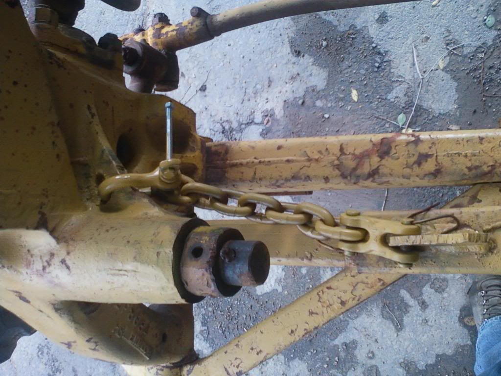
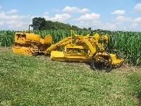
Thanks Deas, Hopefully I can get around to tightening those things dialed in soon. Here are the pics I promised.
Chain on the left side.
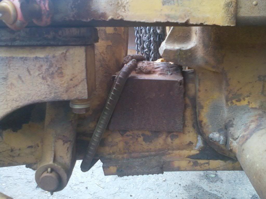
Some plate cluster on the right side, also evidently to keep it from leaning over too far.
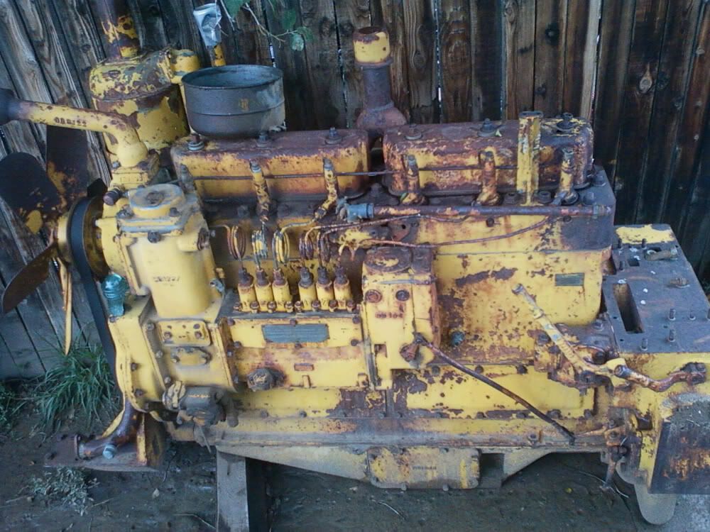
Here is the extra engine, It is not frozen up, that is about all I know on it
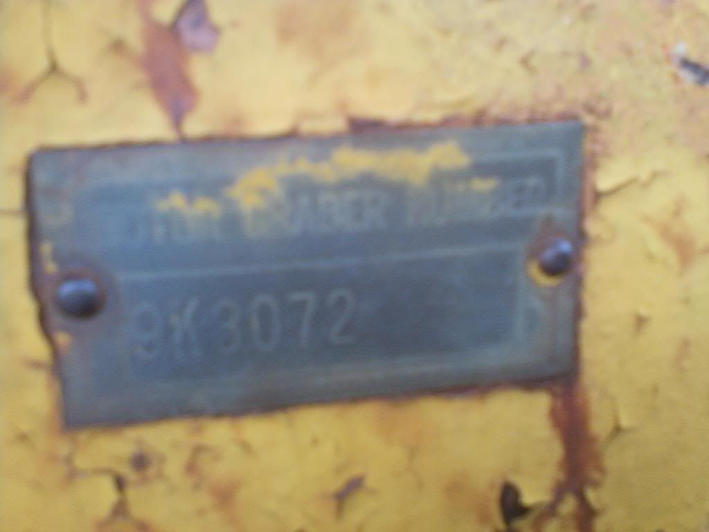
Tag "9K3072" Can anyone tell me anything about it?
Chain on the left side.
Some plate cluster on the right side, also evidently to keep it from leaning over too far.
Here is the extra engine, It is not frozen up, that is about all I know on it
Tag "9K3072" Can anyone tell me anything about it?
Please Log in or Create an account to join the conversation.
- Deas Plant.
-
- Offline
- Platinum Boarder
- User
Less
More
- Posts: 6637
- Thank you received: 928
13 years 2 months ago #63263
by Deas Plant.
You have a wonderful day. Best wishes. Deas Plant.
Replied by Deas Plant. on topic Odd additions.
Hi, Grader Dude.
Yer welkum too ther adjustment information, M8.
I think I can see what they were trying to accomplish with the chain and the extra plate - limiting front axle oscillation - although the 'why' of it does have me getting splinters under my fingernails scratching from my head. One possible reason that comes to mind is that the bushes and/or shaft in the axle pivot may be 'slightly' worn, allowing the axle to oscillate further than normal but methinks it would need to oscillate a LOT further than normal to cause any real problem.
There are normally no wear plates on top of the axle. The stops on the casting simply hit on the top of the axle beam. I have occasionally slid a wedge between the axle and the stop to get me home in the event of a flat front tyre. The Outback of Australia - or the Outback of anywhere for that matter - can bring out all sorts of resourcefulness when the need arises.
Feel free to ask any questions about those adjustments.
You have a wonderful day. Best wishes. Deas Plant.
Please Log in or Create an account to join the conversation.
- chriscokid
-
- Offline
- Platinum Boarder
- Member
Less
More
- Posts: 3363
- Thank you received: 21
13 years 2 months ago #63265
by chriscokid
Replied by chriscokid on topic Hello Guys!
the 9K series is a 12 motor grader engine in my book.
Others can give you more info
Others can give you more info
Please Log in or Create an account to join the conversation.
13 years 2 months ago #63272
by ol Grump
Replied by ol Grump on topic Hello Guys!
I'm gonna have to go along with Deas on that. .it doesn't make sense. I think I'd get the gas axe out and carefully carve some of that mess out of there and give it a try.
Incidentally, I did check the lean angles on my 12. .front wheels lean to 25 degrees either way.
Incidentally, I did check the lean angles on my 12. .front wheels lean to 25 degrees either way.
Please Log in or Create an account to join the conversation.
13 years 2 months ago #63287
by edb
Replied by edb on topic Worn Front End
Hi Team,
good info from Deas on adjustments.
By the look of the "super" shim under the lean wheel rack the entire front end is worn out. When all the pivot points get past being "well worn" the front end will just flop over to full lean when ever it gets past about half way, often the bar bends up and the teeth loose mesh as it crashes to full lean, sometimes going beyond the rack stops--the blank tooth at each end of the rack, . There also looks to be a fish plate added to the lean wheel bar, usually in an attempt to stop the bar distorting and/or the bar cracked thru one of the rack bolt holes.
The axle beam also looks to have been tubbed up at the junction to the lean wheel box casting--common place to crack on hard used units.
At The Dealer we boasted at least one Cat Grader in Every Shire in the State of Victoria here in OZ. As a result, along with all the Contractors units, we had a good turn over in rebuilding front end components. Graders were one of our main stays.
It is a big and costly job to redo one of these front ends if you are not able to do it yourself.
Cheers,
Eddie B.
Please Log in or Create an account to join the conversation.
- Grader Dude
-
Topic Author
- Offline
- Junior Boarder
- User
Less
More
- Posts: 33
- Thank you received: 0
13 years 2 months ago #63306
by Grader Dude
Replied by Grader Dude on topic Hello Guys!
Thanks for the words of wisdom Eddie, although thats not what I was hoping to hear.  If the gears in the lean wheel rack are all in good shape, what are the chances of it falling over on its own?
If the gears in the lean wheel rack are all in good shape, what are the chances of it falling over on its own? Please Log in or Create an account to join the conversation.
- Deas Plant.
-
- Offline
- Platinum Boarder
- User
Less
More
- Posts: 6637
- Thank you received: 928
13 years 2 months ago #63340
by Deas Plant.
You have a wonderful day. Best wishes. Deas Plant.
Replied by Deas Plant. on topic Falling over?????????????????????
Hi, Grader Dude.
Somewhere in the back of what passes for my mind, there seems to be lurking a vague memory that worn bushes, gears, etc., in the angle drive box on the right side of the main frame above and behind the lean wheel drive box on the front axle can contribute to the lean wheels being like a woman of easy virtue - - - - - - LOOSE. The teeth on the drive pinion and the rack need to be meshing properly as well. As EDB said in an earlier post, this is one adjustment where you add shims to improve the meshing rather than taking them out.
Again as EDB said, IF you can do the work yourself, rebuilding the front end is not as daunting a process as having it done, especially if you have some friends who want to play with it when it's a 'goer', some strong backs allied with some weak minds and a generous helping of mechanical savvy - - - - - and maybe a stock of cold 'slabs' (cartons of beer for you topsiders). An FBH might also be useful - - - IF judiciously applied when and where needed. Be prepared to spend some hard-earned on bushes and pins. I also seem to remember that some of those pivot points don't have bushes - the parent metal IS the bearing. If this is the case, they will need to be either rebuilt and line bored or bored and sleeved.
I just can't seem to lose the feeling that there might have been some trauma around the center pivot of that front axle at some time. Why else all the 'jewellery'?
Hope this helps.
You have a wonderful day. Best wishes. Deas Plant.
Please Log in or Create an account to join the conversation.
- Grader Dude
-
Topic Author
- Offline
- Junior Boarder
- User
Less
More
- Posts: 33
- Thank you received: 0
13 years 2 months ago #63377
by Grader Dude
I am feeling the same way, I cant imagine someone would put all that crap on there for no reason. The whole wheel lean assy. is sloppy, most of it is in the linkages to the gearboxes, I will post pics later but it doesn't look like out outta be too hard to shim them or something to keep from blowing apart.
Replied by Grader Dude on topic Hello Guys!
I just can't seem to lose the feeling that there might have been some trauma around the center pivot of that front axle at some time. Why else all the 'jewellery'?
Hope this helps.
I am feeling the same way, I cant imagine someone would put all that crap on there for no reason. The whole wheel lean assy. is sloppy, most of it is in the linkages to the gearboxes, I will post pics later but it doesn't look like out outta be too hard to shim them or something to keep from blowing apart.
Please Log in or Create an account to join the conversation.
Time to create page: 0.184 seconds
ACMOC
Antique Caterpillar Machinery Owners Club
1115 Madison St NE # 1117
Salem, OR 97301
support@acmoc.org
Become a Member!
"I became a member recently because the wealth of knowledge here is priceless."
- Chris R
"I also joined a year ago. had been on here a couple of times as a non-member and found the info very helpful so I got a one year subscription (not very expensive at all) to try it out. I really like all the resources on here so I just got a three year. I think its a very small price for what you can get out of this site."
- Jason N