This should cover it.....
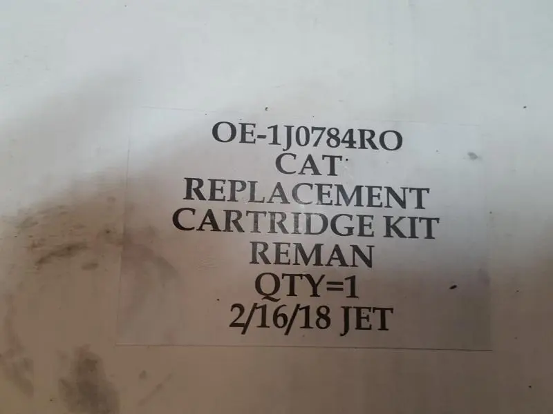
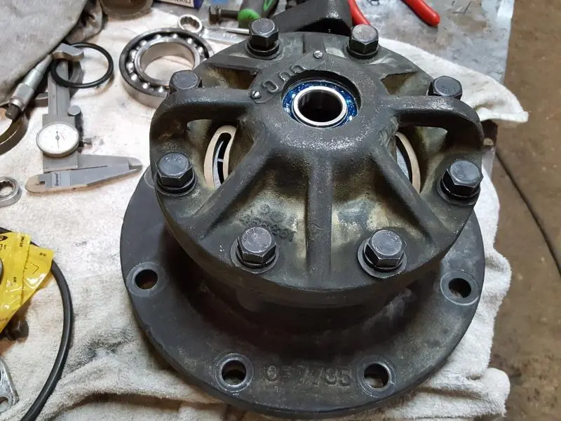
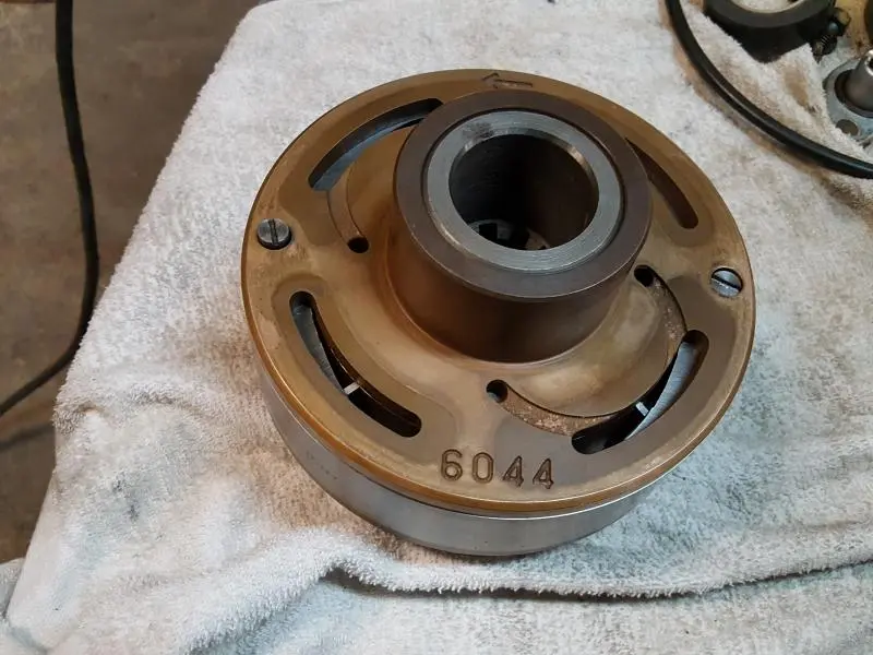
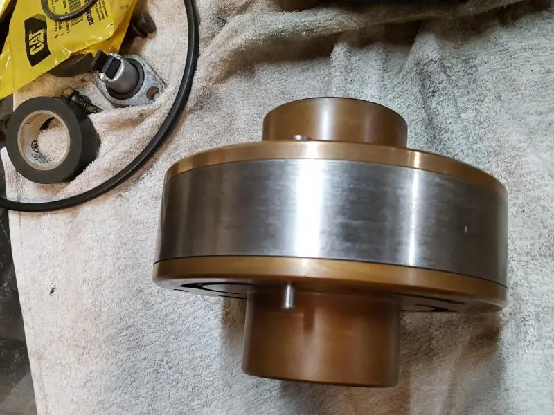
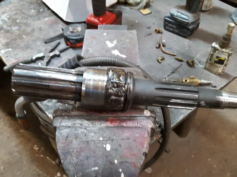

Thanks OM. I think that did cover it. Brian Boaz (Later) How simple this was. I have the new cartridge in the pump body ready to put back into the 46 Hydraulic Control. The old cartridge was worn out.(Photo3) [attachment=47337]20180222_205206.jpg[/attachment][attachment=47338]20180222_205027.jpg[/attachment][attachment=47342]20180215_114653.jpg[/attachment][attachment=47340]20180222_205137.jpg[/attachment][attachment=47339]20180222_205128.jpg[/attachment][attachment=47341]20180222_205148_001.jpg[/attachment]The new cartridge is installed in the pump housing (photo 2) Photos 4 and 5 shows what the new cartridge looks like out of the pump housing. As soon as I turn the shaft (Photo 6) for the new large bearing it will be ready to install in the pump with new seals and bearings. With the shaft inserted into the cartridge as it sets and turned by hand you can feel the pressure building on the output side of the pump. This is put together dry, so with oil this pump should be like new. The entire pump and valve once installed in the Control runs in oil so it will lubricated on start-up. This cartridge according to Caterpillar has been discontinued although Fabric Cat of St. Louis, MO has a used parts section which found this cartridge in the box (Photo 1) To be a used part it sure looks new to me. I have no idea where he found it but Flint Hydraulics in Tennessee has a listing for this Cartridge. $925.00 I think with a $300.00 core charge. Fabric Cat of St Louis, MO had this one for $550 delivered. I think this was a good deal. I look forward to getting the unit back together to see if we have new life in an old hydraulic unit.
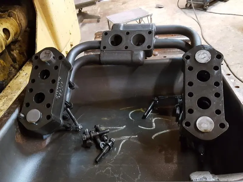
OM Does your book on the 46 Control unit show how the housing assembly (9F6471) is positioned on the Tube assembly (9F1559)? I have had the tube assembly off once before and I remember one of the housings was assembled with the spring pushing the piston in the housing toward the rear and the other side was pushing the piston toward the front of the unit. I turned them both so the springs were pushing the piston toward the rear of the unit as in picture. Is this the correct way this is suppose to go together?[attachment=47366]20180223_093446.jpg[/attachment]
All the springs should be mounted in the same direction with springs toward the rear. Direction determined by the flow schematic to the lift cylinders and viewing the parts diagram. I could not find a definitive illustration.
OM I found a Servicemen's Reference Book (FORM FEO 12914-02) on E-bay, CATERPILLAR HYDRAULIC CONTROLS AND EQUIPMENT, which covers the No. 44, No. 46, and No. 41 hydraulic controls. The pistons and springs in the manifold valves in the above photo are correct. The spring goes to the front of the manifold valve and the piston to the rear. The illustration also shows the pistons and springs like they are suppose to be. This is what the book said about the later manifold valve along with the illustration attached. Interesting how it works. Brian Boaz
[attachment=47468]20180302_171250_001.jpg[/attachment]
LATER NO. 46 HYDRAULIC CONTROLS EQUIPPED
WITH MANIFORLD VALVE ARRANGEMENT
Later No. 46 Hydraulic Controls are equipped with a manifold valve arrangement consisting of four sleeve-type valves which are housed two each in separate valve housings. This arrangement gives faster blade drop. The housings are located between the internal tube assembly and the related tube assembly pads located in the lower portion of the control tank at either side. The original counterbalance control valve, float check valve and counterbalance valve found in earlier hydraulic controls are no longer used due to the addition of the manifold valve arrangement. A field replacement group is available, which makes possible the installation of the manifold type valve arrangement in earlier hydraulic controls which are in use in the field.
The purpose of the manifold valve arrangement is to permit the entry of oil from the supply reservoir into the hydraulic lines when a deficit of oil exist.
Such a deficit of oil is due to either a sudden rise of fall of the bulldozer blade which is faster than the hydraulic pump can supply pressure oil to the pump side of the hydraulic cylinder pistons. When this occurs, a void of oil exist within the hydraulic lines and cylinders between the pump side of the cylinder pistons and the supply tank. This causes a pressure differential which is great enough to open the manifold valve. This void of oil is present for a very short time since the hydraulic pump quickly regains the necessary supply of oil with the help of oil entering the hydraulic lines from the oil reservoir through the manifold valves.
These controls have also had a slight change made to the oil dump valve. The older type is replaced with one very similar in appearance but having a drilled passage to permit oil to pass through it to the maximum pressure relief valve. The new type dump valve is also included in the field replacement group mentioned earlier.
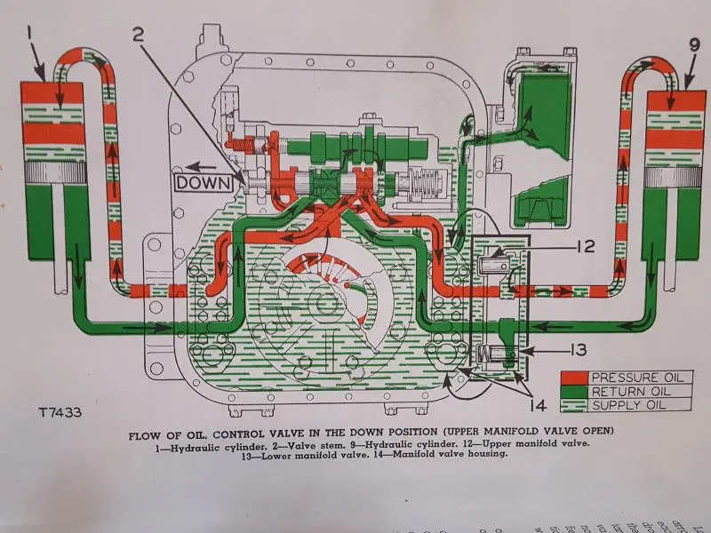
FLOW OF OIL-CONTROL VALVE IN THE DOWN POSITION
(UPPER MANIFOLD VALVE OPEN)
The flow of oil in hydraulic controls having the manifold valve arrangement (with a few exceptions) is very similar to that shown for having the float check, counterbalance and counterbalance control valves in use. The following describes in detail the flow of oil as shown in the accompanying illustration. The illustration shows the manifold valve action with the control valve stem (2) moved into the down position. One of the two manifold valve assemblies consisting of two sleeve valves each is shown in the inset at the lower right side of the illustration. The assemblies are identical, therefore, on side only is illustrated.
When the bulldozer blade lowers suddenly from the raised position against little or no resistance, an oil deficit occurs in the upper of head ends of the hydraulic cylinders (1) and (9). The deficit of oil is the results of a momentary under-supply of oil from the pressure side of the hydraulic pump. The cylinder pistons travel downward in the cylinders at a greater rate of speed than the pump can supply oil to fill the upper portion or head end of the cylinder.
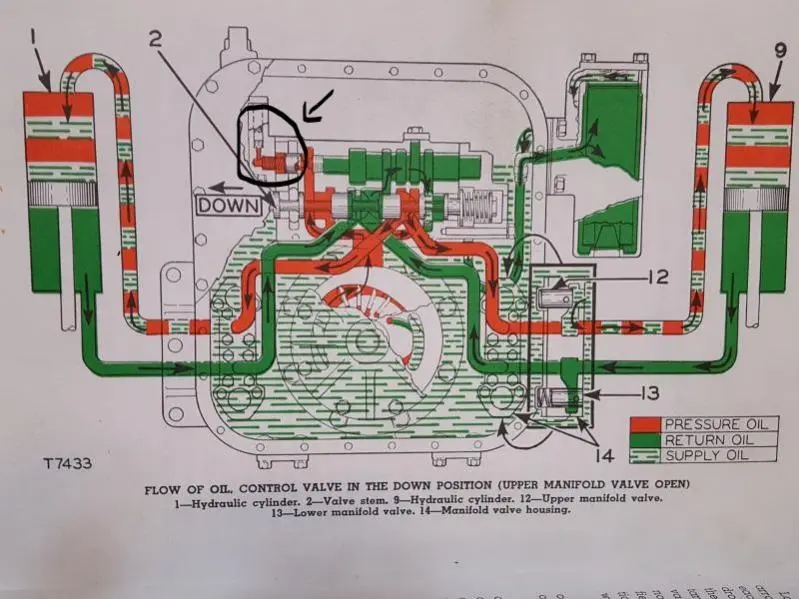
Oil is discharged from the rod end of the cylinders to the supply reservoir at a greater rate of flow than the hydraulic pump removes the oil from the reservoir. This in turn creates a slight pressure differential between the pump side of the piston and the supplyu tank. When this pressure reaches approximately 3 PSI, the valve (12) (one on each side of the control) open permitting supply oil to enter the lines from tlhe reservoir and flow directly to the head end of the cylinders.
The supply oil merges with oil flowing from the pressure side of the pump within the manifold valve housing (14) and continues to enter the lines until the void is eliminated.
The valve (13) located in the return oil side of the manifold valve assembly remains inactive since there is no differential of pressure.
The manifold valve act in the float position of the control in the same manner as the float check valve in earlier model controls with one exception. In the later hydraulic controls, the oil to overcome the deficit is delivered to the cylinders directly from the supply reservoir through the manifold valve assemblies. On the earlier model controls, the oil to overcome the deficit is delivered from the reservoir to the cylinders through the float check valve and the main control valve.
I have and was using that same manual but could not conclude for sure what orientation the springs and pistons should be in from the service manual but the springs are shown to the rear in the parts manual. With the parts in front of me I'd try checking where those piston ports line up with the housing. That should determine what the orientation should be.
Here's the parts diagram. I'm assuming pistons are not shown as separate parts as they are match bored to the housings and should not be interchanged.
Hi Team,
I would think that the valve closed end faces should have left witness marks on their mating surfaces that would have indicated the correct orientation.
Been a long time but I feel this was my double check back in the 60's.
From memory, they are selective fitted as well so need to be re-fitted in same bores as originally fitted to.
Cheers,
Eddie B.
All the springs should be mounted in the same direction with springs toward the rear. Direction determined by the flow schematic to the lift cylinders and viewing the parts diagram. I could not find a definitive illustration.
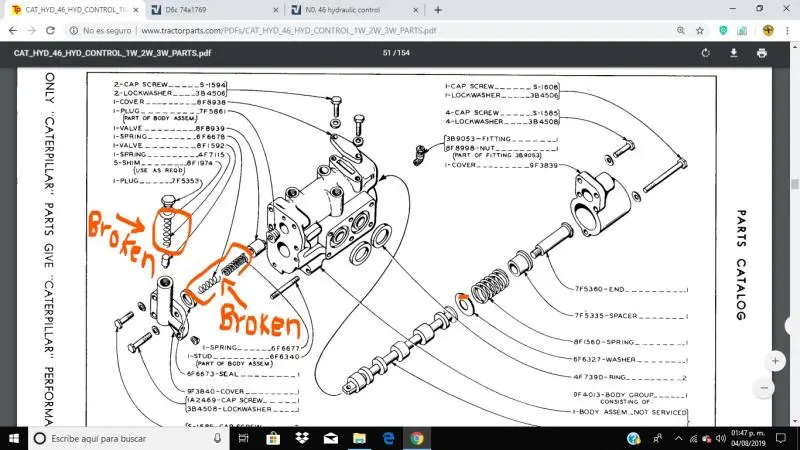
Good morning sir, sorry for the inconvenience if you are so kind, could you give me some specifications of hydraulic control # 46 I have a pump that tilts some cylinders but it has no force to lift them, I found broken springs in the valve I want to know if this is the root of the problem I leave an image showing the part where the broken springs are and if you can tell me what kind of valves are there. Thank you.
[attachment=54938]InkedHYD 46--1_LI.jpg[/attachment][attachment=54938]InkedHYD 46--1_LI.jpg[/attachment]


Our channel highlights machines from the earliest Holt and Best track-type tractors, equipment from the start of Caterpillar in 1925, up to units built in the mid-1960s.
Chapter Two
| Highacres Farm, Dewey Lane, Brackenfield, Derbyshire DE55 6DB, UKChapter Nineteen
| Victoria Park, Urana NSWChapter Nineteen
| 1234 Carngham-Lake Goldsmith Rd, Lake Goldsmith Vic
Antique Caterpillar
Machinery Owners Club
1115 Madison St NE # 1117
Salem, OR 97301
Terms & Privacy
Website developed by
AdCo
"I became a member recently because the wealth of knowledge here is priceless."
-Chris R