Can't remove rack and do any good. Just have to work around it.
The trick is to make sure the lifter you are working on is rising as you come up to the TDC Mark for that cylinder pair. That cylinder will be on compression stroke and you can turn engine in normal direction up to stop exactly on the mark. This takes out the effect of any gear wear between crankshaft and accessory shaft/injection pump drive. The other cylinder listed on that flywheel mark will not have its corresponding pump lifter rising as you come up to the mark.
When you have finished setting the lifter to spec, turn the engine a little past tdc and recheck your depth. The plunger should still be rising a little, ensuring you have set the right lifter for that TDC stop.
Hi Niels,
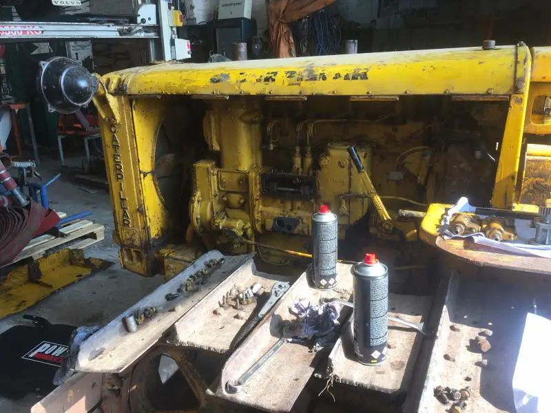
the rack can be removed by taking out the bolt holding the coupling link (fork 2A3311) to the round rack rod and the square rack slide bar.
Next remove the bolts holding the square rack slide bar retaining plates (2A3327) and the square rack slide bar can be removed.
All the injection pumps can be installed before the square rack slide bar--to refit the bar, refit the Injection Pumps, then ensure the timing lines on the Inj. Pump plunger gears are facing out and central--fit the bar ensuring all the timing marks are aligned--or the bar can be fitted and then the plungers and then the pump bodies to their respective plungers. I usually did the Inj. Pumps fitting first then the bar last--choice is yours.
Before trying to adjust the lifters be VERY sure that the Flywheel is fitted to the correct position on the crankshaft--these older engines do not have a offset flywheel bolt, and it is well known for the flywheel to be fitted in the wrong position--this means that the Top Dead Center (TDC) marks do not line up correctly to the pointer in the flywheel housing window when each cylinder is at its true TDC.
Check this by removing the valve cover and observing if, say No 4 cyl. has its valves rocking (tight) then No 1 cyl. should be at TDC Compression Stroke (valves loose) and the Injection pump plunger is rising for the lifter set position.
I have seen several/worked on engines with incorrectly orientated (fitted) flywheels when at The Dealer and since.
If you find it is out then you will need to make new marks to go by.
When turning the engine to the TDC position for timing checking/adjustment, always turn the engine to the TDC mark in the Direction of Rotation only--if you go past the TDC mark then turn the engine backwards some 60 degrees and come back up to the TDC position again--this takes up any slack or wear out of the Injection Pump drive system that may cause an error in your adjusting measurements.
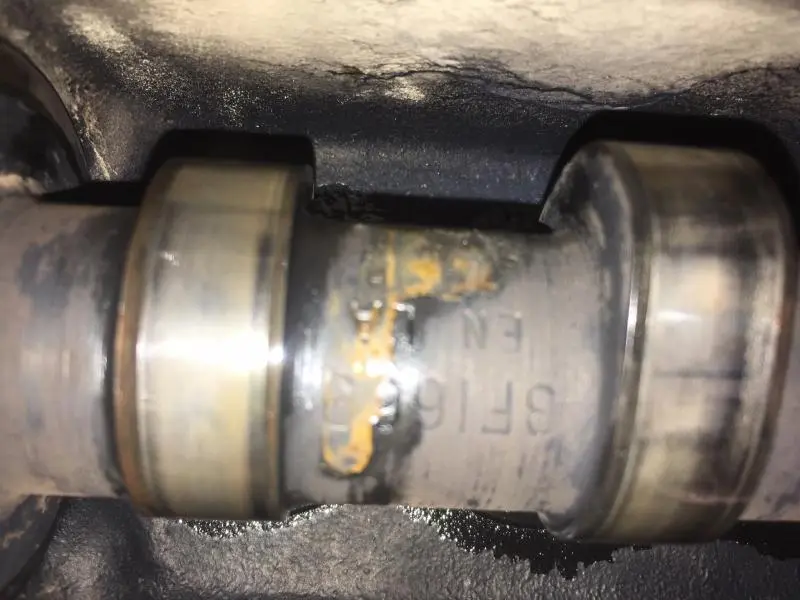
By my Caterpillar Fuel Injection Pump Housings Book (Form No 7272D) the lifter setting On Engine at TDC is given as 1.734" +/- 0.002" for engines with Inj. Pump camshaft part numbers :- 2A5559, 7B5584, 3F1669--the P/No is forged into the body of the actual camshaft itself --cannot recall if the outer plate has the camshaft P/No given-- inside the Inj. Pump--remove bottom Inj. Pump cover and turn engine until the P/No is visible to confirm it.
The lifter setting is different for any other P/No Camshafts. You will need to inform me if it is a different P/No so I can give these lifter dimensions--D4 should be what I gave you above.
I usually set the lifter setting so the lifter is higher--least measurement--ie. 1.732"--or close to--as this may allow for wear on the Inj. Pump Plunger end and in the Inj. Pump drive system, and so keep the timing correct or slightly advanced for better starting and running.
Hope this helps.
Cheers,
Eddie B.

CCjercy and edb,
Thanks for your reply!
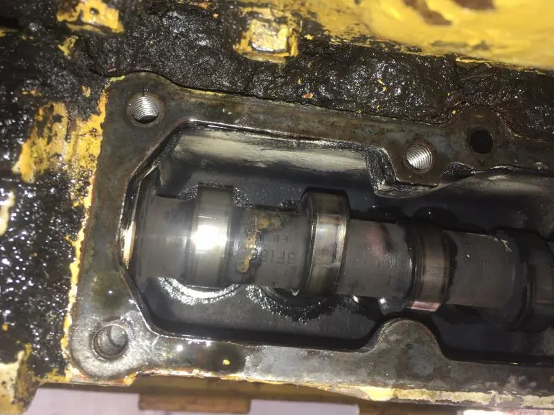
I did remove the rack, so have a lot more space now to adjust and place the plungers back in the correct way.
Did check for the number on the camshaft and it reads 3F1669, no number on the housing!
Next thing to check is if the flywheel is mounted correctly, so if that's ok I can start adjusting the lifters.
Thanks Niels
[attachment=53393]IMG_1950.jpg[/attachment][attachment=53392]IMG_1949.jpg[/attachment][attachment=53391]IMG_1947.jpg[/attachment][attachment=53390]IMG_1946.jpg[/attachment][attachment=53389]IMG_1933.jpg[/attachment][attachment=53388]IMG_1932.jpg[/attachment][attachment=53387]IMG_1931.jpg[/attachment]
Hi Niels,
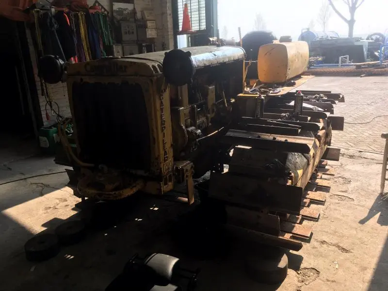
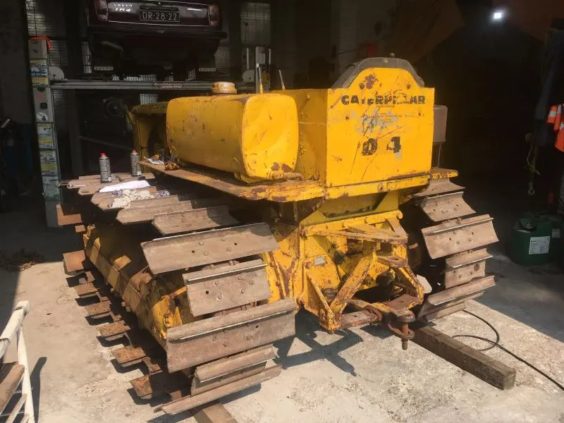
thanks for the pictures and feed back of your nice tidy looking machine.
Love the working lights and the staggered grouser shoe look.
Cheers,
Eddie B.
[attachment=53399]PHOTO-2019-04-09-12-58-08.jpg[/attachment]He EdB,
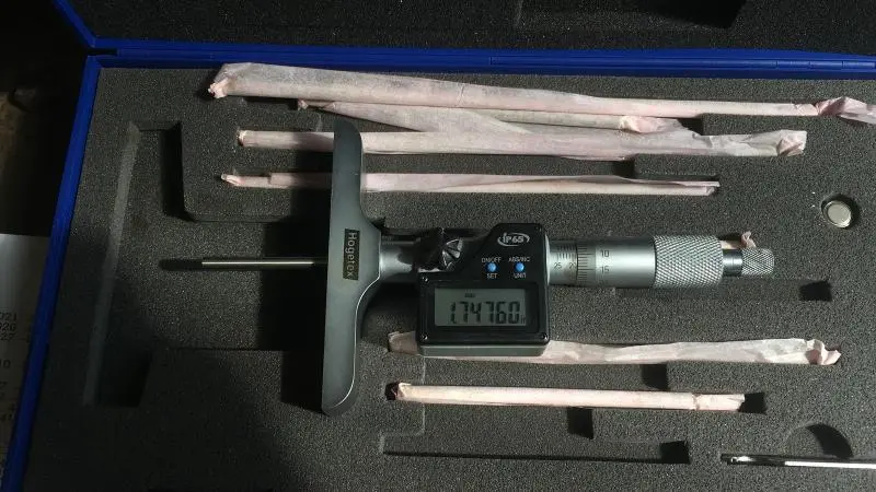
On the picture you see the result off checking the setting on lifter no 1.
After checking TC was right, I first was 360 degree fault.
This means that the fuel is entering the precombustion chaimber to late not?
They cut the grousers because in the heavy clay it was floating to much by plowing...!
That tractor would have been quite a "swamper" with those pads all full width! Once had two D69U parts tractors here with wide pads and towing winches. They were from a logging operation. I am sorry they aren't still around.
Yes. The high number means late injection of fuel into the chamber.
Do you have any pictures of the rack and pumps in that tractor? I am used to the later models and didn't realize the rack could come out that easily.
[quote="nielske"]He EdB,
On the picture you see the result off checking the setting on lifter no 1.
After checking TC was right, I first was 360 degree fault.
This means that the fuel is entering the precombustion chaimber to late not?
They cut the grousers because in the heavy clay it was floating to much by plowing...![/quote]
What you need are the 20" pads with the tapered trousers, that way you are less likely to snag something than with the offset edges you have
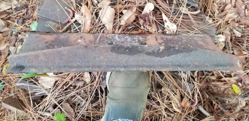
Here is a 20" tapered from a 5U


Our channel highlights machines from the earliest Holt and Best track-type tractors, equipment from the start of Caterpillar in 1925, up to units built in the mid-1960s.
Antique Caterpillar
Machinery Owners Club
1115 Madison St NE # 1117
Salem, OR 97301
Terms & Privacy
Website developed by
AdCo
"I also joined a year ago. had been on here a couple of times as a non-member and found the info very helpful so I got a one year subscription (not very expensive at all) to try it out. I really like all the resources on here so I just got a three year. I think its a very small price for what you can get out of this site."
-Jason N
