You are correct.
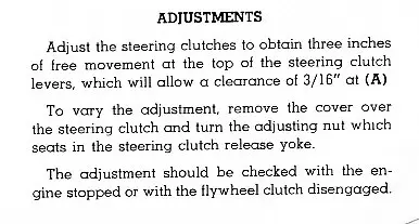
The motion of the steering clutch levers is toward the rear in the center of the tractor, the crank that the steering clutch booster pushes on rotates toward the center of the tractor, pulling the steering clutches apart and compressing the springs. As the clutches wear thinner, the engaged position moves away from the centerline of the tractor and takes up more and more of the slack in the linkage. Screwing the adjuster nuts away from the centerline of the tractor on each side will return the crank, push rod and lever to their proper position.
One thing to note before you adjust to 3" is to ensure the levers both go fully forward against the stops and there is no debris preventing them from hitting the bumpers at the base of the levers.
While you're in there, you may need to adjust the brakes as well, the adjusters are right there in the same cover. Do you have a rear cable control on it? That makes it hard to actually see what your fingers are touching at the same time!
Did you find the steering clutch release bearing grease fittings under the seat?
If you get time, please post pictures of your project and tractor.

Thanks for the thumbs up about which way to move the adjusting nut and the explanation of how the steering clutches move. Yes, I did grease the two clutch release bearings and both levers are returning to their bumpers.....Now I just have to see if I have a wrench big enough to get on that adjusting screw, I hope it is an easy turner.
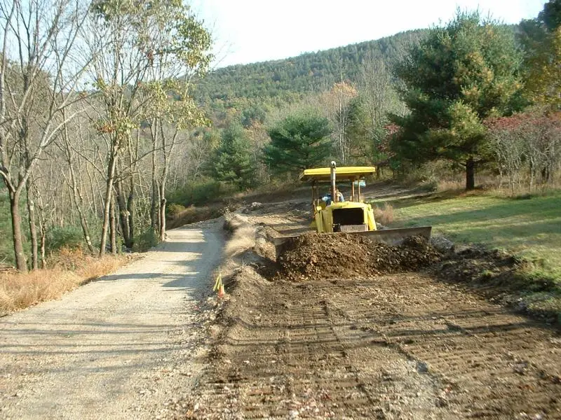
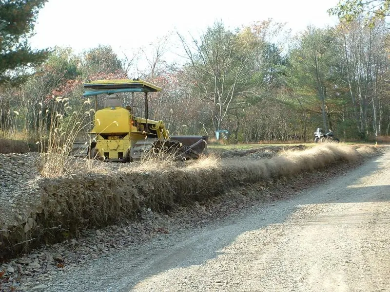
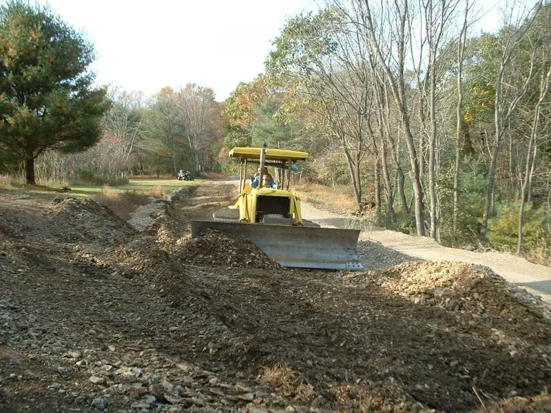
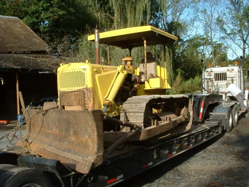
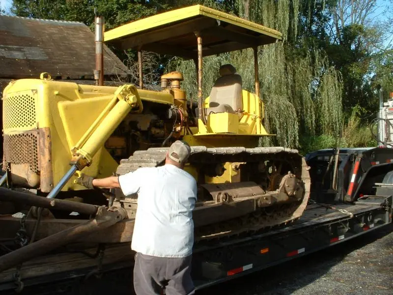
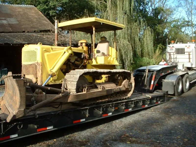
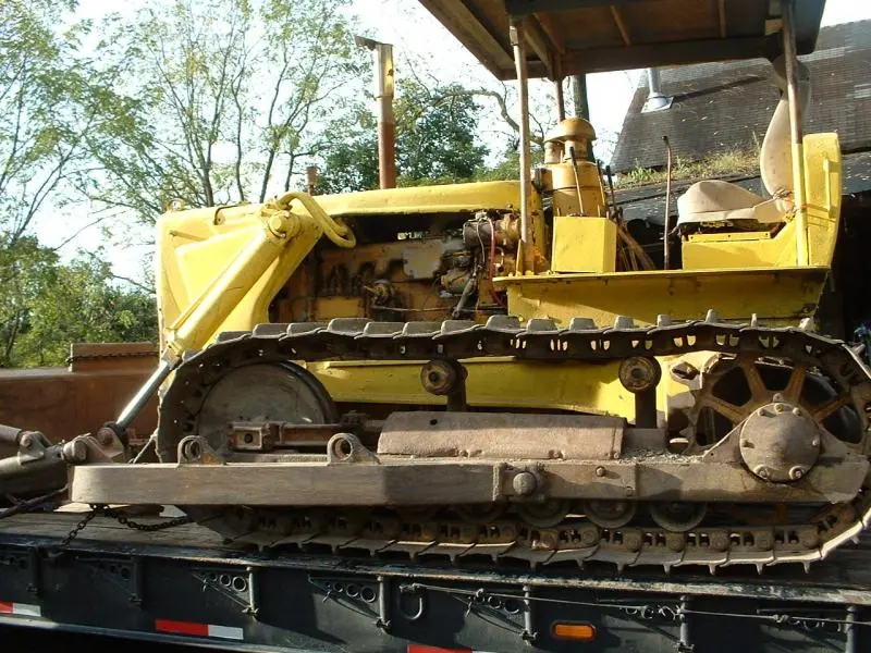
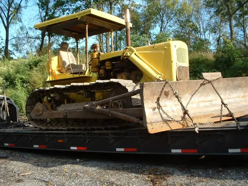
I have included a few pictures of my tractor as it was being chained down for the ride home a few months ago and a few pictures of the dozer pushing some shale.
John
[attachment=15393]D6 002.jpg[/attachment][attachment=15392]D6 003.jpg[/attachment][attachment=15391]D6 004.jpg[/attachment][attachment=15389]D6 006.jpg[/attachment][attachment=15388]Bulldozer & pumpkins 008.jpg[/attachment][attachment=15387]Bulldozer & pumpkins 012.jpg[/attachment][attachment=15386]Bulldozer & pumpkins 014.jpg[/attachment][attachment=15390]D6 005.jpg[/attachment][attachment=15394]D6 001.jpg[/attachment]
That big nut is 1 5/8 and they are always fun if you don't have the fuel tank off,unless it turns by hand once unlocked.Nice looking tractor,good luck on your project.
Ray
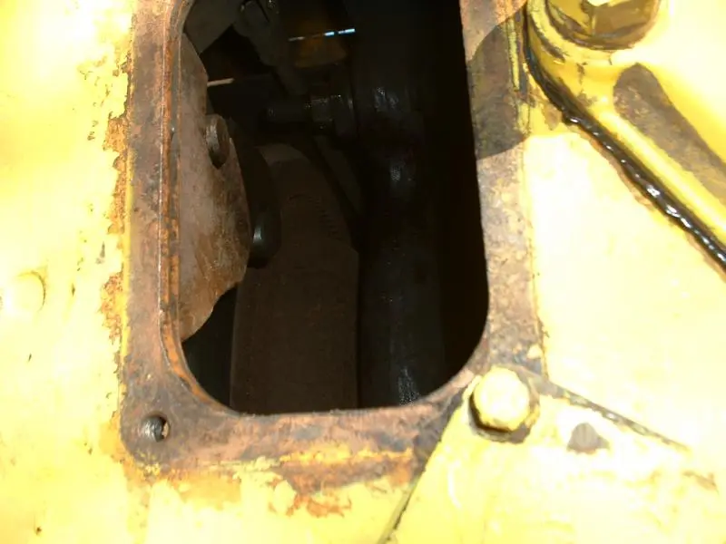
I could not turn the lock nut through the opening on top of the steering clutch case. I could just barely get the wrench on the nut but there was no room to turn it. I was just about ready to give up in disgust, when I noticed there was an access cover on the back of the steering clutch case. I removed the four bolts and I had a view of the adjusting nut from below. Here again I could get a wrench on the lock nut but there was no room to turn it as the wrench was too long. I got a pair of vise grips on the lock nut and they were short enough to turn and I got the lock nut loose. Once the lock nut broke loose, I could turn it with my fingers and I backed it off about one half inch on the bolt. I tried and the adjusting nut also turned with my fingers and I backed it off until it hit the lock nut. Climbed up on the tractor and tried the lever but.... no joy...there was still no free play, it was the same as before.
I figured maybe start the tractor and use the steering clutch a bit and the adjustment will show up....but still no change.
Pretty much stumped at this point and open to suggestions.
Hey Ray54 thanks for the good words and the size of that big nut. Next time Iam at the flea market I will keep an eye open for an old 1 5/8 wrench. I can then cut it down and make a stubby which will work in that small area.
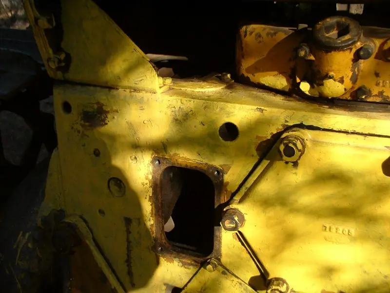
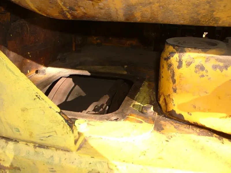
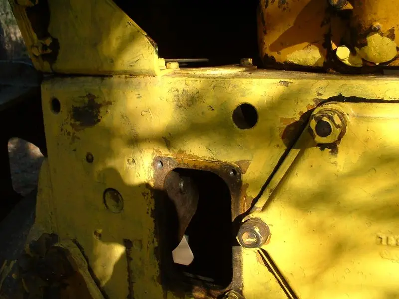
I took a few pictures of the two openings on the left side of the tractor.
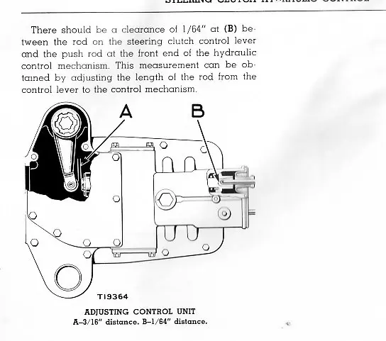
With the clutch disengaged or the engine stopped, there sbould be no oil pressure to take up the free travel even if the push rod is keeping the valve actuated. Still, clean out and ensure someone hasn't adjusted the pushrods out too far.
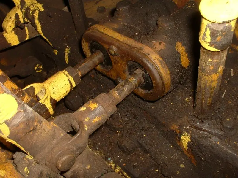
Today I removed some of the floor panels and took a picture of how it looked on the front end of the steering clutch hydraulic control mechanism....then I cleaned some of the surface dirt off and took a second picture....What do you guys think?
I would really like to know what the guy was thinking when he slopped that lemon yellow paint over everything!
John
Hello...
I have the same crawler and had the same sort of problems.
I ended up removing the fuel tank and then cleaning up everything.
Then removed the pump cover and started from scratch.
I asked a lot of questions so I could understand how and what everything does.
Do a search of my posts, it was only a couple months ago.
Once It was adjusted to spec everything works pretty good, especially when you consider its 50 plus years old.
If didn't have the folks here helping me I would still be scratching my head.
Regards Chris


Our channel highlights machines from the earliest Holt and Best track-type tractors, equipment from the start of Caterpillar in 1925, up to units built in the mid-1960s.
Antique Caterpillar
Machinery Owners Club
1115 Madison St NE # 1117
Salem, OR 97301
Terms & Privacy
Website developed by
AdCo
"I also joined a year ago. had been on here a couple of times as a non-member and found the info very helpful so I got a one year subscription (not very expensive at all) to try it out. I really like all the resources on here so I just got a three year. I think its a very small price for what you can get out of this site."
-Jason N