ACMOC
Login
ACMOC
D4 dozer hydraulics.

D4 dozer hydraulics.

Showing 1 to 10 of 13 results
1
d2davie
Topic Author
Offline
Send a private message to d2davie
Posts: 13
Thank you received: 0
Does anyone have pictures of a cat d4 7u dozer with a twin spool 44 hyd unit fitted. Going to make up pipe work to work a 40 scraper so would have to run the 4 pipes back along the top of the wing but the winch controls seem to get in the way of that plan, I was wondering how cat overcome this problem,thanks .
Please log in or create an account to join the conversation.
Sun, Mar 11, 2007 5:52 AM
SJ
Offline
Send a private message to SJ
Posts: 1,890
Thank you received: 0
I can,t quite picture what the problem is there but could you adapt hoses along with the pipes to work or would that be a problem too?
Please log in or create an account to join the conversation.
Sun, Mar 11, 2007 6:43 AM
Old Magnet
Offline
Send a private message to Old Magnet
Posts: 16,696
Thank you received: 18
Reply to SJ:
I can,t quite picture what the problem is there but could you adapt hoses along with the pipes to work or would that be a problem too?
hello d2 davie,
I have the lines for the double valve winch application but they are currently off the tractor.
As far as installation the 44 lever stand moved to the outside edge of the fender, then the winch control, then the lines have 90 degree offsets to the inside around the winch control. The lines from the transfer valve stay stacked all the way. The through lines are stacked until you get past the winch lever, just ahead of the seat where they offset to stack above the other two lines (now four lines stacked) as they go around the tank seat. My installation got somewhat buggered up when they split the winch control bracket in order to route the lines around the ROPS installation but the lines were only slightly tweaked. If no one comes up with an original installation picture in a couple of days I will post some pictures of the lines if you like.

Maybe I jumped the gun.....I'm assuming you have the tank seat model for which the above description fits.
Please log in or create an account to join the conversation.
Sun, Mar 11, 2007 8:26 AM
d2davie
Topic Author
Offline
Send a private message to d2davie
Posts: 13
Thank you received: 0
Reply to Old Magnet:
hello d2 davie,
I have the lines for the double valve winch application but they are currently off the tractor.
As far as installation the 44 lever stand moved to the outside edge of the fender, then the winch control, then the lines have 90 degree offsets to the inside around the winch control. The lines from the transfer valve stay stacked all the way. The through lines are stacked until you get past the winch lever, just ahead of the seat where they offset to stack above the other two lines (now four lines stacked) as they go around the tank seat. My installation got somewhat buggered up when they split the winch control bracket in order to route the lines around the ROPS installation but the lines were only slightly tweaked. If no one comes up with an original installation picture in a couple of days I will post some pictures of the lines if you like.

Maybe I jumped the gun.....I'm assuming you have the tank seat model for which the above description fits.
Thanks for replying guys, old magnet your spot on it does have a tank seat I was wondering about moving the control lever bracket, a picture of the cat setup would be great thanks.
Please log in or create an account to join the conversation.
Sun, Mar 11, 2007 5:56 PM
Toolbox
Offline
Send a private message to Toolbox
Posts: 82
Thank you received: 0
Reply to d2davie:
Thanks for replying guys, old magnet your spot on it does have a tank seat I was wondering about moving the control lever bracket, a picture of the cat setup would be great thanks.
I have a 7U with a double unit. One for the #4 Toolbar and one out the back for implements. When the wife gets home from her Grandmother's I'll try and get some pictures, if it ain't to dark in the shed. She is the camera pro and then I'll have to see if I can figure out the pictur posting thing.
Please log in or create an account to join the conversation.
Sun, Mar 11, 2007 11:26 PM
Old Magnet
Offline
Send a private message to Old Magnet
Posts: 16,696
Thank you received: 18
Reply to Toolbox:
I have a 7U with a double unit. One for the #4 Toolbar and one out the back for implements. When the wife gets home from her Grandmother's I'll try and get some pictures, if it ain't to dark in the shed. She is the camera pro and then I'll have to see if I can figure out the pictur posting thing.
Hi toolbox,
It's the winch installation that makes the normal setup different. The extra bends and routing changes to miss the winch control bracket and the winch brake lever makes it different than the normal four line set up. Does yours have the D4N Hyster winch?
Please log in or create an account to join the conversation.
Sun, Mar 11, 2007 11:41 PM
Toolbox
Offline
Send a private message to Toolbox
Posts: 82
Thank you received: 0
Reply to Old Magnet:
Hi toolbox,
It's the winch installation that makes the normal setup different. The extra bends and routing changes to miss the winch control bracket and the winch brake lever makes it different than the normal four line set up. Does yours have the D4N Hyster winch?
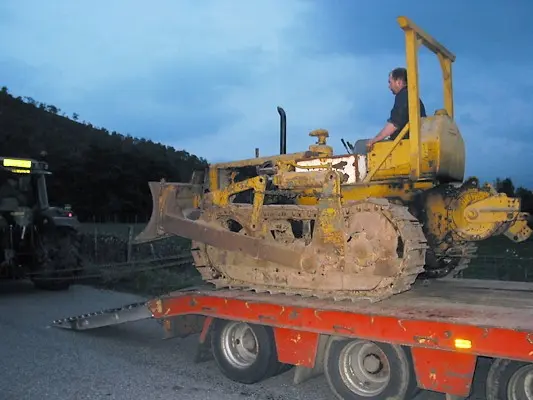
Sorry it took so long to get back. Things went to sh#! at work I have been busy. OM, no mine does not have a winch, I've got a 540 RPM pto and a homemade cab. I guess I did not read the post close enough. I still need to figure out the picture posting deal though.
Please log in or create an account to join the conversation.
Thu, Mar 15, 2007 10:13 AM
d2davie
Topic Author
Offline
Send a private message to d2davie
Posts: 13
Thank you received: 0
Reply to Toolbox:
Sorry it took so long to get back. Things went to sh#! at work I have been busy. OM, no mine does not have a winch, I've got a 540 RPM pto and a homemade cab. I guess I did not read the post close enough. I still need to figure out the picture posting deal though.
Thanks anyway toolbox, I will try to post a pic.
Attachment
Please log in or create an account to join the conversation.
Thu, Mar 15, 2007 8:56 PM
Old Magnet
Offline
Send a private message to Old Magnet
Posts: 16,696
Thank you received: 18
Reply to d2davie:
Thanks anyway toolbox, I will try to post a pic.
Attachment
Hi d2 davie,
I did some more investigating of my hydraulic lines and concluded mine is probably not the best reference. As I mentioned my installation has been altered for the ROPS. I took some pictures anyway and researched the lines (still had the part number tags on them) and find them to be the standard units used for a four pipe installation. The set that go to the transfer valve is pt # 8F8443, the straight through set is pt # 8F8440. For my installation they had to get the four pipes stacked to get past the ROPS support but in checking dimensions I see no reason why the stacked pairs would not fit and still miss the winch brake lever.
On this particular installation the control lever bracket was moved so that is 1-1/2 in. from the edge of the fender.
Hope this helps.
Please log in or create an account to join the conversation.
Fri, Mar 16, 2007 8:02 AM
d2davie
Topic Author
Offline
Send a private message to d2davie
Posts: 13
Thank you received: 0
Reply to Old Magnet:
Hi d2 davie,
I did some more investigating of my hydraulic lines and concluded mine is probably not the best reference. As I mentioned my installation has been altered for the ROPS. I took some pictures anyway and researched the lines (still had the part number tags on them) and find them to be the standard units used for a four pipe installation. The set that go to the transfer valve is pt # 8F8443, the straight through set is pt # 8F8440. For my installation they had to get the four pipes stacked to get past the ROPS support but in checking dimensions I see no reason why the stacked pairs would not fit and still miss the winch brake lever.
On this particular installation the control lever bracket was moved so that is 1-1/2 in. from the edge of the fender.
Hope this helps.
Thanks old magnet for the part numbers and pics. I will have to move the handbrake lever for the winch and the control lever to make the make the pipe work look as origional as possible will post some pics when finnished, thanks again. (d2 davie)
Please log in or create an account to join the conversation.
Fri, Mar 16, 2007 2:30 PM
Old Magnet
Offline
Send a private message to Old Magnet
Posts: 16,696
Thank you received: 18
Reply to d2davie:
Thanks old magnet for the part numbers and pics. I will have to move the handbrake lever for the winch and the control lever to make the make the pipe work look as origional as possible will post some pics when finnished, thanks again. (d2 davie)
Here are some specs and you can make out the two brackets for winch control and valve control (no rear lines though)
Please log in or create an account to join the conversation.
Sat, Mar 17, 2007 3:12 AM
Showing 1 to 10 of 13 results
1
YouTube Video Placeholder

Follow Us on Social Media

Our channel highlights machines from the earliest Holt and Best track-type tractors, equipment from the start of Caterpillar in 1925, up to units built in the mid-1960s.

Upcoming Events

Cromford Steam Rally

Chapter Two

| Highacres Farm, Dewey Lane, Brackenfield, Derbyshire DE55 6DB, UK

The Century of Caterpillar

| Elkader, 203 Johnson St, Elkader, IA 52043, USA

100 YEARS OF CATERPILLAR IN TASMANIA

Chapter Nineteen

| 2 Winkleigh Rd, Exeter TAS 7275
View Calendar
ACMOC

Antique Caterpillar
Machinery Owners Club

1115 Madison St NE # 1117
Salem, OR 97301

[email protected]

Terms & Privacy
Website developed by AdCo

Testimonials

"I also joined a year ago. had been on here a couple of times as a non-member and found the info very helpful so I got a one year subscription (not very expensive at all) to try it out. I really like all the resources on here so I just got a three year. I think its a very small price for what you can get out of this site."
-Jason N

Join Today!