Sounds like the threads are not screwing down into the precombustion chamber. Take a rotary wire brush and clean the threads of the Pre-cup and make sure the trheads on the injector nut are not damaged.
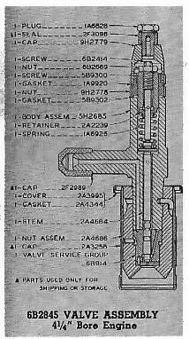
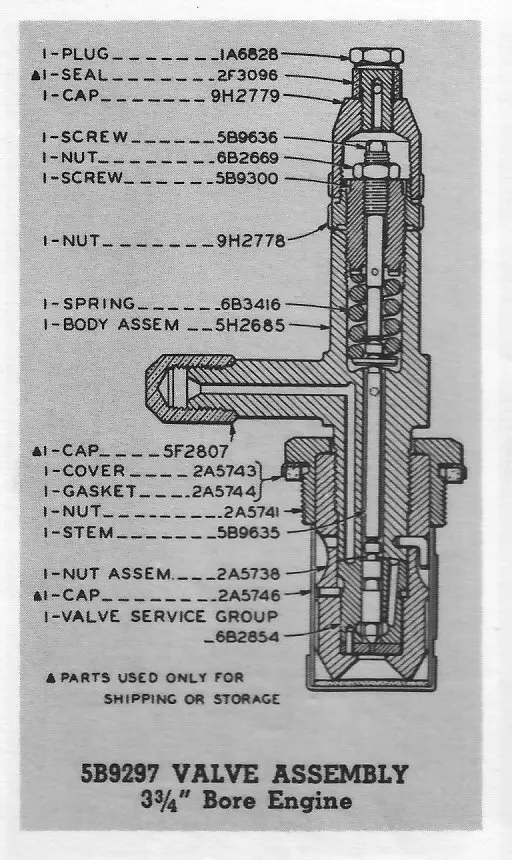
Have you tried it without the cork gasket under the big nut? I cannot see any copper washers in the parts book, though there may be some included in the valve assembly 5B9297 as CAT calls the injector.
The threads are in the precombustion chamber, not the head. I am unfamiliar with the appearance of those chambers. I have a couple sets, but in the engines and have never had them out yet. In the parts book they appear to be a single piece chamber which seals into the cylinder combustion chamber with a copper washer. There is an o-ring around the chamber that seals the water jacket so it doesn't leak to the outside.
I believe the chambers are installed with a male hex driver, torqued down and then a set screw that comes in from the side is tightened to prevent it backing out when the injectors are removed. I cannot fathom the reason for a second set of threads unless they were used in the manufacture of the chambers.
We need Eddie B!
Are you sure you have all the right parts?
No bottom gasket is used, seal is direct to pre-com chamber.
Setting has nothing to do with fit.
[quote="Old Magnet"]Are you sure you have all the right parts?
No bottom gasket is used, seal is direct to pre-com chamber.
Setting has nothing to do with fit.[/quote]
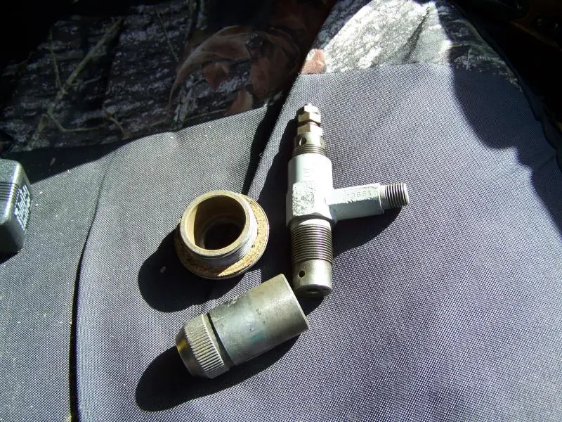
three are the ones I took out and the fourth is a replacement (I have a habit of marking things). As I understand it the small nuts on the top of the injector have nothing to do with the seating but serve to adjust the cracking pressure.
I called the guy who rebuilt them and he said that I'm missing parts but I have everything shown in the (poor quality) diagram in the reproduction manual it seems, and everything we can remember taking out. I can work on a nuclear reactor but this is kicking my butt. this is another disassembled and without guts
[attachment=17219]cat inj.jpg[/attachment]
Pre-com chamber should look like the one on the left in the attached picture.
Hi Team,
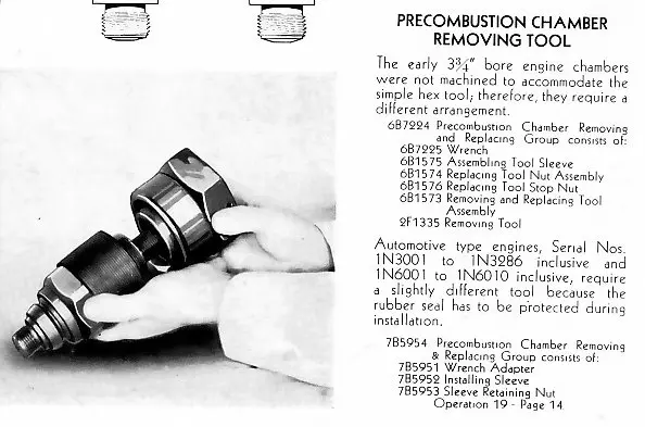
the early D3400/D2 uses pre-chambers that are different to all others. They are screwed in and out using two opposing threads within the chamber opening using a special tool.
From memory there can be two different length Spray Valve (S V) retaining nuts for the 4 1/4" bore D4 engines due to the early ones being held in by the clamp arrangement--later ones used the nut type retention, but, I am sure the D2 were only ever nut retained.
Both the D2 and D4 injectors use mostly all the same parts including the retention nuts when needed for the later D4.
The I V retaining nuts for the clamp type are longer in the body and there is not enough clearance to fit the retention nut--you have to use the short S V retaining nut for the nut type retention system as the nut flange is too thick to fit correctly.
All this means if the main retention nuts spin on the injector body all should be as designed or else the nut would be tightly jammed between the body and S V retaining nut and the Injection Valve (Spray Valve) service group would be loose inside the injector--it may appear tight due to the injection valve spring tension--if this condition were so, then if the injector was tested for Valve Opening Pressure fuel would leak everywhere and the injector would not function.
I guess this means there is some possible thread problem as regards depth that the nut can screw into the pre-chamber and therefore not clamp the injector onto its tapered metal to metal seat -- no gaskets.
The cork gasket up under the tin shield is only a seal against dirt, water, etc. getting down into the pre-chamber/injector area. The gasket has a slight crush applied to it by flexing of the tin shield.
Sorry for the confused answer but it not exactly straight forward and easy to explain--anti-Vietnam pills do not help.
Hope scans below help.
Cheers,
Eddie B.


Our channel highlights machines from the earliest Holt and Best track-type tractors, equipment from the start of Caterpillar in 1925, up to units built in the mid-1960s.
Chapter Fifteen
| Placerville, CAChapter Nineteen
| 1234 Carngham-Lake Goldsmith Rd, Lake Goldsmith, Victoria, 3373, AustraliaChapter Two
| Stradsett, Nr Downham Market. Norfolk PE33 9HA UKChapter Two
| Faulkner Farm, West Drove, Wisbech, Cambridgeshire, PE14 7DP, UK
Antique Caterpillar
Machinery Owners Club
1115 Madison St NE # 1117
Salem, OR 97301
Terms & Privacy
Website developed by
AdCo
"I also joined a year ago. had been on here a couple of times as a non-member and found the info very helpful so I got a one year subscription (not very expensive at all) to try it out. I really like all the resources on here so I just got a three year. I think its a very small price for what you can get out of this site."
-Jason N