Hi terry,
it is simply a matter of unbolting the rubber "pucks" to enable the engine to be lifted out. You are right that the engine cannot slide forward due to the hard bar interfering with the engine sump.
The two pumps mounted in the front of the trans may need to be removed also to gain clearance or at least the two lower flywheel housing cover plate bolts need to come out to clear the pumps---too long since I did one.
The rear flange of the coupling is on a spline on the Torque Convertor input shaft but can come only come out once the pucks have been removed.
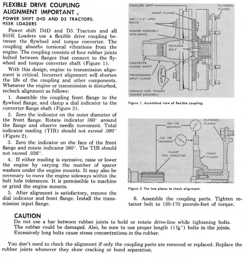
There are shims fitted under the front and rear engine mounts to align the coupling. If the coupling is out of alignment even a little bit the pucks fail at early hours, and, if out a lot the crank thrust bearing can fail.
Below is the method for aligning the coupling. As the 941-951 has the D4D Trans this is the correct method for your machine.
You cannot mount the dial indicator to the Torque Convertor Flange as it is a slip coupling and thus has clearance in the splines making the flange wobble about and give a false reading on the dial indicator. You need to make up a 90Deg piece of suitable size round bar to clamp to the T/C output spline for mounting the dial indicator to, a worm drive hose clamp or two will do to act as a clamping medium.
I think if you left click on the scan three times it will come up to a readable size.
Hope this helps.
Now all you blokes, grab this scan while it is up as you know the drill it will be removed in due course to post other good stuff I have as needed !!!!!
Cheers,
Eddie B.
You have a wonderful day. Best wishes. Deas Plant.
Hi, EDB.
That is a good page to have for any owner of a 941, 951 or 955. I have had to remove and replace some of those couplings and they AIN'T easy. It would be a whole lot harder if the engine was locked up as in this case. That may mean they will have to remove the rear belly plate, another FUN job.
Long arms and LONG patience also help.
Spot on I have only posted two issues here and both got me the info I needed fast
Great board with great guys
Thanks Terry
Terry, pay very close attention to the alignment in the pages Eddy posted. Try to get as close to zero as you can. If you don't do it right the biscuits will rip out in a week.
Later Bob
Yes that is obvious.
From my perspective I fix the engine others do the re install so it will not be my problem . I will pass the info to them of course.
To clarify my background is generator sets and engines. I have little knowledge of the layout of the cat in question having never seen it .
Thanks again
Terry
Just got the engine here.strangest 3304 I ever saw its a D330.
I am looking for an overhaul gasket set for it. My cat source wasn't real encouraging. but I suspect there are sources out there.
Again thanks in advance
Terry


Our channel highlights machines from the earliest Holt and Best track-type tractors, equipment from the start of Caterpillar in 1925, up to units built in the mid-1960s.
Chapter Nineteen
| 1234 Carngham - Lake Goldsmith Road Lake Goldsmith VIC 3373Chapter Two
| Folds Farm, Godshillwood, Fordingbridge, Hampshire, SP6 2LU
Antique Caterpillar
Machinery Owners Club
1115 Madison St NE # 1117
Salem, OR 97301
Terms & Privacy
Website developed by
AdCo
"I became a member recently because the wealth of knowledge here is priceless."
-Chris R