Quick check on the alternator, does it magnetize the back of the alternator over the rear bearing? If it does, it's exciting and you probably have a bad connection somewhere. You should also check the voltage output at the stud on the back with it running. Also check for battery voltage at the output stud when the engine is stopped (unless you have a battery disconnect on the system) No voltage at the output stud means no circuit to the battery so no charge on the ammeter.
I don't think the direction of rotation makes a difference. There have been some arguments about the effectiveness of the fan if you turn the thing backwards, but that's another issue. "normal" rotation is clockwise facing the drive end/counter-clockwise facing the output end, but again I don't think it matters.......It's an alternator after all.
Is yours a Delco? Direct drive conversion? Or a belt drive from?????
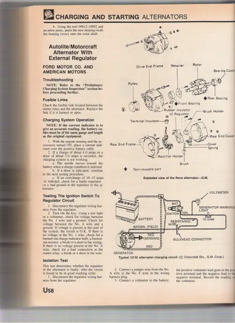
On the Delco 10SI which is used for many of these, the regulator terminal from the switch is the one on the left looking at the rear of the alternator (output stud is to the left and regulator plug is at the top) The heavy wire on the right, going into the same plug, is commonly attached to the output stud by a short jumper in a conversion where there isn't a wire in the harness to attach it to.
Most common problem is not turning fast enough, but if your regulator wire from the switch is hot it should excite at a relatively low rpm compared to the one-wire setups.
Thanks folks. .the ideas put forth were pretty much what I'd thought. Guess it's time to recheck the wiring with a VOM to see if I've got a broken wire somewhere.
Paul
Sometimes alternators have slinger fans that work best when the fan "throws" the air outwards. Otherwise, it doesn't matter.
Cheers,
Neil.
I'm about ready to start pulling out what hair I have left on this one😠 . .or maybe set an injector up to the pump and hit it with a torch and see how much hair and beard I have left afterwards😮 per OM's suggestion.
What's happening is this: it's a direct drive conversion with an adapter that fits where the generator was. Wiring is direct from the large terminal to the battery with the red jumper wired to the terminal, the white wire through a switch and then to battery. Per ccjersey's question, yup, the back of the alternator does magnetize. All wires have been checked and rechecked, switch replaced several times and continuity checked. Everything checks out but yet, no movement of the ammeter and it's been replaced twice now too.
I finally broke down and ordered a laser tachometer as I'm not sure I'm getting enough revs at high idle. By marking the front pulley and turning the fan, it looks like the alternator is overdriven by around 1 to 1.125 or so. So at around 1000 engine RPM, the alternator should be turning around 1125 RPM.
At this point, I'm almost ready to get the original generator overhauled and try a 12 volt regulator. .almost!
Any suggestions? Sacrificing a tender young lady is out of the question. .there are no schools in this town however I HAVE been wondering if Matilda the Hun would work in this case. . . .
Are you saying that the cable from the + terminal on the alternator is going directly to the battery, then the ammeter will not show a charge because there is nothing passing through it,look at the pictures below,its for a one wire alternator but it will give you an idea how things should be hooked up.
AJ
Here's a couple more wiring diagrams. Same ones I sent "director" (congratulations) "7U puller" that he used to straighten out the D6 wiring mess.
If you are magnetizing the back of the alternator then you are producing power some of the alternator conversions on the old IH tractors they just put voltage meters on them that way did't have to fight amp meter. If this is an internal regulated alternator you need to make sure that the sencing voltage wire (not the batery wire that hooks to the back of the alternator) the sencing wire has to either have a switch or a diode in line or it will back feed and run battery dead. I have put alternators on some H's and B farmalls and they don't turn very fast.
Russell


Our channel highlights machines from the earliest Holt and Best track-type tractors, equipment from the start of Caterpillar in 1925, up to units built in the mid-1960s.
Chapter Two
| Highacres Farm, Dewey Lane, Brackenfield, Derbyshire DE55 6DB, UKChapter Nineteen
| 2 Winkleigh Rd, Exeter TAS 7275
Antique Caterpillar
Machinery Owners Club
1115 Madison St NE # 1117
Salem, OR 97301
Terms & Privacy
Website developed by
AdCo
"I also joined a year ago. had been on here a couple of times as a non-member and found the info very helpful so I got a one year subscription (not very expensive at all) to try it out. I really like all the resources on here so I just got a three year. I think its a very small price for what you can get out of this site."
-Jason N