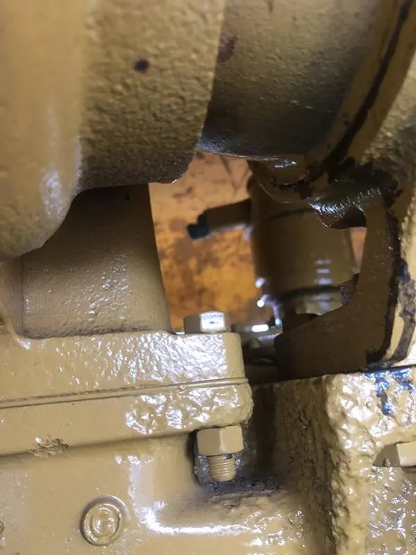
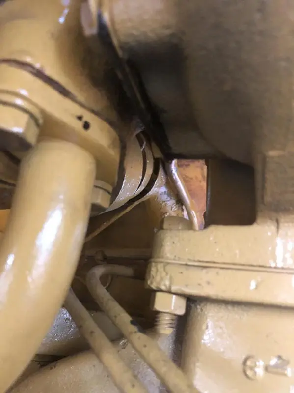
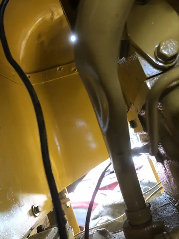
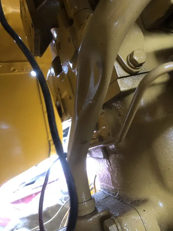
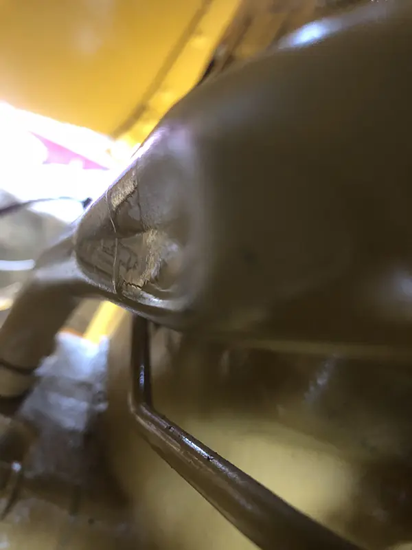
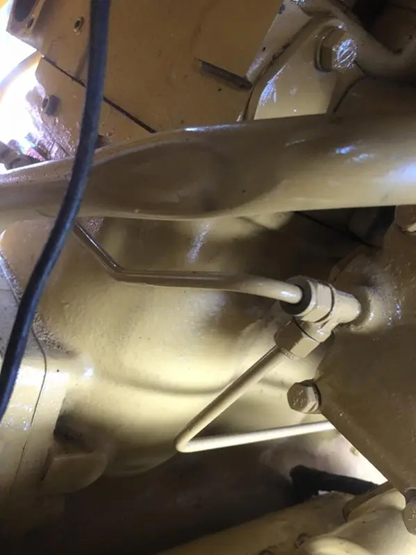
That's a pretty good ding in the drain line, pretty restrictive for a gravity flow. I'd definitely fix or replace.
A tooth off with an injection pump can go either way, to lean one way, to rich the other with rich affecting the idle speed more.
Is this that 3Xxxxx engine if I recall right, should be new enough to get a replacement line.
Hello OM
No this is the 90A284 engine out of a 950 loader that I am fitting into my 944. I will repair the drain line and see what happens. 2S3108 is the part number and it shows up as Indirect Replacement Available which means no longer available.
So the idle speed is high but smooth and the engine will shut down cleanly. I assumed if one was out on the rack then the engine idle would be rough and it would be a rough shut down as one cylinder would be still firing.
Regards
Phil
Swantrax in Hazelmere Western Aus. shows having one and some here in the US listed through Machinery Trader Parts. +61 8 6280 2110
Hi Team,
I too believe you have enough drain line restriction to cause a backup oil oil in the turbo.
If you cannot get anew tube I would scribe a line along the axis of the tube so as to re-orientate any bends, cut the tube through the middle of the ding and work from each end on the half ding length to panel beat ot the ding and then reweld being sure to orientate the scribe lines.
If a injection pump element quadrant gear was one tooth advanced or retarded you would have one cylinder acting as described by PhilC above.
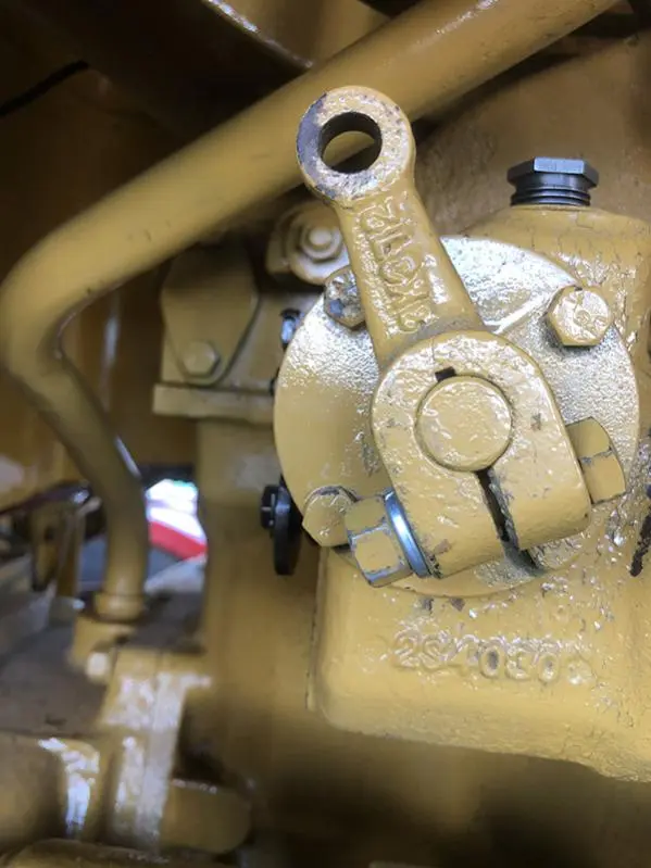
For the fast idle I would first disconnect the Gov. Control Rod from the Gov. Control Lever at the Inj. Pump and see if the linkage needs lengthening. Then check and see you can still get to High idle--Full Gov. position.
There may be a difference in the Gov Control lever lengths between the two engines that Could change the linkage ratios enough to cause a shortened stroke condition/rotation angle of the Gov. Control Shaft.
If your Gov Control lever is splined to the Gov. control shaft you may only need to re-orientate the Gov. control lever a spline or so the get within range
I seem to recall there maybe a stop bolt that can limit the accelerator pedal angle downwards so to not over-stress the linkage within the Governor--maybe 1/8" clearance when the pedal is lightly pushed down by hand. It is located up under said pedal at the operators station, also seem to recall that the said pedal comes to a fairly vertical position when it is in the Shut Off position.
Cheers,
Eddie B.
Hello All
I thought of a few different ways to fix the dent and in the end I took the tube and capped both ends, hooked it up to a compressor and heated the dent until it popped out. I refitted it this afternoon and ran the engine and it did seem to fix the problem. When I removed the tube I remembered the reason I thought it would not matter as the tube itself is 7/8"ID but the end that goes into the flywheel housing has a fitting for an o-ring that reduces the diameter to 5/8"ID.
Eddie the Gov Control lever is keyed to the shaft so it can't be indexed but it would not help anyway. The accelerator linkage is free to move in either direction. I could not find a stop bolt. The governor has the low oil pressure lock but it seems to release fine. I think I will have to remove the end cover and see if I can see anything that would cause the high idle. I don't think the low idle adjustment screw was touching the linkage inside as it was very free to move in either direction and the lever did not move at all.
Also would the high idle cause the diesel knock to sound worse than it should?
Does anyone know the replacement part number for the 7m6001 tachometer?
Regards
Phil

How did you position the rack before installing the pumps?
I built a little fixture from a bushing that would fit in the access hole after the little cover was removed and which the rack would fit inside. It had a nut welded in one end and I screwed a bolt through until the tip of it was recessed the proper dimension and locked it with a jamb nut. If I remember correctly there was some (Little) spring tension pushing back against the fixture as it was pushed home against the face of the pump housing.
Hi Team,
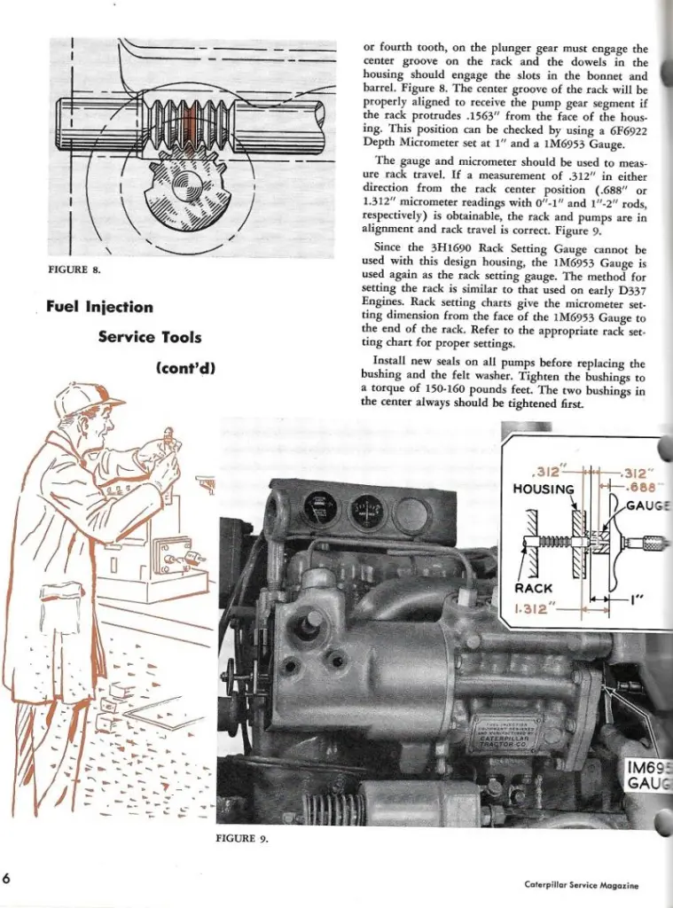
if you had the Cat 8M0530 Gauge ( Rack micrometer), you would read 0.000 on it BUT, if using a depth mike and the Cat 1M6953 Gauge/spacer the measurement is 1" as said above.
NOW, assuming you have none of these tools, in actual fact, the rack protrudes the actual Injection Pump front mounting face (down inside the bore under the 2 bolt cover) by 0.1563" to be at Zero rack position for installing your pump elements as outlined in the scan below.
NOTE
the rack travel check dimensions in either direction (in or out) to ensure you have the pump gears aligned correctly--alas, the dimensions are for when using the Gauge as outlined--but are NOTED as being a movement of 0.312" in either direction of the Zero position to be aligned correctly.
Hope this helps.
Cheers,
Eddie B.
[quote="ccjersey"]How did you position the rack before installing the pumps?
I built a little fixture from a bushing that would fit in the access hole after the little cover was removed and which the rack would fit inside. It had a nut welded in one end and I screwed a bolt through until the tip of it was recessed the proper dimension and locked it with a jamb nut. If I remember correctly there was some (Little) spring tension pushing back against the fixture as it was pushed home against the face of the pump housing.[/quote]
I made something similar up that used the bolt hole for the cap. I thought I had the correct dimensions as per the workshop manual.
[quote="edb"]Hi Team,
if you had the Cat 8M0530 Gauge ( Rack micrometer), you would read 0.000 on it BUT, if using a depth mike and the Cat 1M6953 Gauge/spacer the measurement is 1" as said above.
NOW, assuming you have none of these tools, in actual fact, the rack protrudes the actual Injection Pump front mounting face (down inside the bore under the 2 bolt cover) by 0.1563" to be at Zero rack position for installing your pump elements as outlined in the scan below.
NOTE
the rack travel check dimensions in either direction (in or out) to ensure you have the pump gears aligned correctly--alas, the dimensions are for when using the Gauge as outlined--but are NOTED as being a movement of 0.312" in either direction of the Zero position to be aligned correctly.
Hope this helps.
Cheers,
Eddie B.[/quote]
Thanks Eddie. I could not procure either the 8M0530 nor the 1M6953 so I made my own. I thought I had it all worked out. I do have a depth micrometer somewhere but I cannot find it.
I only get about an hour to work on the 944 each afternoon and I spent that hour today looking for the jig I had made. I hope to have another look at it tomorrow.
Regards
Phil


Our channel highlights machines from the earliest Holt and Best track-type tractors, equipment from the start of Caterpillar in 1925, up to units built in the mid-1960s.
Chapter Nineteen
| Cnr Hiller Lane and Ballarat Road, Hamilton, Vic, 3300Chapter Two
| Pitt Farm, Little Paxton, St Neots, Cambridgeshire, PE19 6HD, UKChapter Fifteen
| Historic Santa Margarita Ranch, 20000 El Camino Real, Santa Margarita, CA 93453, USAChapter Thirty
| Hartley - South Australia
Antique Caterpillar
Machinery Owners Club
1115 Madison St NE # 1117
Salem, OR 97301
Terms & Privacy
Website developed by
AdCo
"I became a member recently because the wealth of knowledge here is priceless."
-Chris R