ACMOC
Login
ACMOC
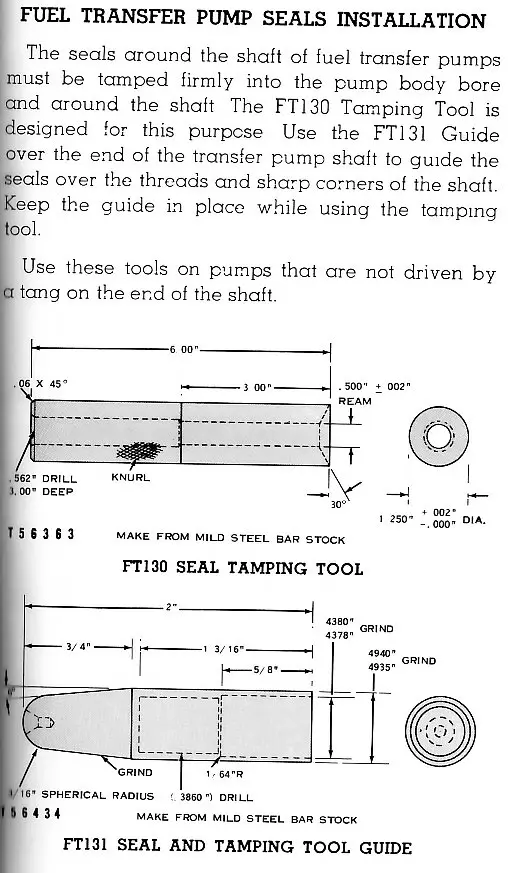
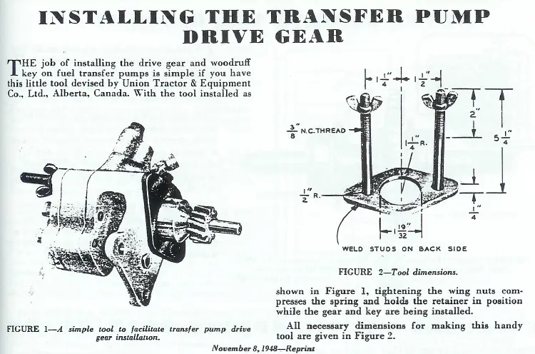
Fuel Transfer Pump Packing Tamping Tools

Fuel Transfer Pump Packing Tamping Tools

Showing 1 to 10 of 45 results
1
edb
Topic Author
Offline
Member
Send a private message to edb
Posts: 4,027
Thank you received: 0
Hi Team,
posting in answer to a PM.
Cheers,
Eddie B.
Attachment
Attachment
Please log in or create an account to join the conversation.
Thu, Jul 19, 2012 7:47 AM
1_sparky
Offline
Send a private message to 1_sparky
Posts: 23
Thank you received: 0
EDB don't wont to jump into your thread but since we are on the subject.

I have A Cat 112 3U grader with the pump in pieces from a rebuild that started 15 - 20 years ago. How much wear on the shaft can the seals withstand? I have slightly less than a thou wear.

Do I need to soak these seals like installing the old water pump packings?


Thanks for posting the tools I will see if I can get a set made now.
Please log in or create an account to join the conversation.
Tue, Jul 24, 2012 4:02 PM
Dandy Dave
Offline
Member
Send a private message to Dandy Dave
Posts: 362
Thank you received: 0
Reply to 1_sparky:
EDB don't wont to jump into your thread but since we are on the subject.

I have A Cat 112 3U grader with the pump in pieces from a rebuild that started 15 - 20 years ago. How much wear on the shaft can the seals withstand? I have slightly less than a thou wear.

Do I need to soak these seals like installing the old water pump packings?


Thanks for posting the tools I will see if I can get a set made now.
0.001 wear on your shaft should not be a problem. The pumps that I have in the past on D-2's, D-4's, and others, I have just replaced the packing supplied from cat and put the transfer pump back together without a problem. The packing spring is so strong that the packing will seat its self. The important part on a transfer pump is to be sure that the bypass valve is clean and working correctly. Dandy Dave!
Please log in or create an account to join the conversation.
Tue, Jul 24, 2012 8:18 PM
edb
Topic Author
Offline
Member
Send a private message to edb
Posts: 4,027
Thank you received: 0
Reply to Dandy Dave:
0.001 wear on your shaft should not be a problem. The pumps that I have in the past on D-2's, D-4's, and others, I have just replaced the packing supplied from cat and put the transfer pump back together without a problem. The packing spring is so strong that the packing will seat its self. The important part on a transfer pump is to be sure that the bypass valve is clean and working correctly. Dandy Dave!
Hi 1-sparky,
no problems Mate, the more info I can get out there for you restorers the better.

As with water pump shafts the packings will crush when tamped to take up a fair amount of wear.
At The Dealer we used to assemble and lube the Transf. Pumps with engine oil. In fact one packing seals fuel and the other seals engine oil, the packings are graphited so engine oil at assembly should be OK.
Never saw or had a return for burned packings from not soaking, so, it must work OK with the graphite and oil.

Dandy Dave,
you, and others, have been lucky with your packings, BUT, in my 8 odd years in The Dealer Fuel Injection Pump Room we saw some, due to fuel dilution, comebacks due to others not tamping the packings.
The tamping is to deform the packing and crush it snuggly around the shaft and to spread the packings in the housing bores.
As strong as the packing spring is, the packings are not always soft enough/old stock to deform and seal around the shaft and out against the housing bore side walls.

Therefore it is my, and Caterpillar's, recommendation to guarantee a good seal that the packings are tamped and sealing to save the risk of fuel dilution in your engine and therefore the risk of taking out your bearings etc.
Yellow Father recommends tamping the Packings and gave us the drawings to make the tooling to do it, so, it is deemed necessary by him. The choice is yours.

Hope this helps.
Cheers,
Eddie B.
Please log in or create an account to join the conversation.
Wed, Jul 25, 2012 7:04 AM
Dandy Dave
Offline
Member
Send a private message to Dandy Dave
Posts: 362
Thank you received: 0
Reply to edb:
Hi 1-sparky,
no problems Mate, the more info I can get out there for you restorers the better.

As with water pump shafts the packings will crush when tamped to take up a fair amount of wear.
At The Dealer we used to assemble and lube the Transf. Pumps with engine oil. In fact one packing seals fuel and the other seals engine oil, the packings are graphited so engine oil at assembly should be OK.
Never saw or had a return for burned packings from not soaking, so, it must work OK with the graphite and oil.

Dandy Dave,
you, and others, have been lucky with your packings, BUT, in my 8 odd years in The Dealer Fuel Injection Pump Room we saw some, due to fuel dilution, comebacks due to others not tamping the packings.
The tamping is to deform the packing and crush it snuggly around the shaft and to spread the packings in the housing bores.
As strong as the packing spring is, the packings are not always soft enough/old stock to deform and seal around the shaft and out against the housing bore side walls.

Therefore it is my, and Caterpillar's, recommendation to guarantee a good seal that the packings are tamped and sealing to save the risk of fuel dilution in your engine and therefore the risk of taking out your bearings etc.
Yellow Father recommends tamping the Packings and gave us the drawings to make the tooling to do it, so, it is deemed necessary by him. The choice is yours.

Hope this helps.
Cheers,
Eddie B.
I guess the ones I have done in the past, maybe a half a dozen or so, I have been lucky with then. If any anymore come along in the future I will note the Cat procedures. Infact, it has been so long since I have been there that I forgot that there were two seals. I do remember the spring being tough though. Luckily I never had any fuel in the oil on any of the rebuilds. I did have a friend with a D-2 at one time that was getting fuel in the oil and it turned out to be the O ring between the injection pump and the filter housing. I remember in the parts book that that little O ring was tough to spot. Thanks, Dandy Dave!
Please log in or create an account to join the conversation.
Wed, Jul 25, 2012 7:39 PM
1_sparky
Offline
Send a private message to 1_sparky
Posts: 23
Thank you received: 0
Reply to Dandy Dave:
I guess the ones I have done in the past, maybe a half a dozen or so, I have been lucky with then. If any anymore come along in the future I will note the Cat procedures. Infact, it has been so long since I have been there that I forgot that there were two seals. I do remember the spring being tough though. Luckily I never had any fuel in the oil on any of the rebuilds. I did have a friend with a D-2 at one time that was getting fuel in the oil and it turned out to be the O ring between the injection pump and the filter housing. I remember in the parts book that that little O ring was tough to spot. Thanks, Dandy Dave!
Thanks everyone it looks like it is getting closer to done.


I was looking at the idler gear yesterday and I see a ring machined into the end of only one side. Since I didn't take it apart does this ring go against the cover or the pump housing?
Please log in or create an account to join the conversation.
Thu, Jul 26, 2012 12:25 AM
edb
Topic Author
Offline
Member
Send a private message to edb
Posts: 4,027
Thank you received: 0
Reply to 1_sparky:
Thanks everyone it looks like it is getting closer to done.


I was looking at the idler gear yesterday and I see a ring machined into the end of only one side. Since I didn't take it apart does this ring go against the cover or the pump housing?
H 1-sparky,
the machined ring faces outwards when installed on the shaft only to show it is an updated drive gear.
Sometime in the past Cat did a design change to the gear and the line identifies the updated gear.
Cheers,
Eddie B.
Please log in or create an account to join the conversation.
Thu, Jul 26, 2012 7:38 AM
1_sparky
Offline
Send a private message to 1_sparky
Posts: 23
Thank you received: 0
Reply to edb:
H 1-sparky,
the machined ring faces outwards when installed on the shaft only to show it is an updated drive gear.
Sometime in the past Cat did a design change to the gear and the line identifies the updated gear.
Cheers,
Eddie B.
Thanks edb I was thinking it was some kind of relief groove. This is on the gear that slides / free floats on the shaft sticking out of the main casting body.


I started to assemble the pump without seals. When the bolts snug by hand I can turn the bare 1/2" drive shaft, but as soon as I torque the bolts down I cant turn the pump with my bare hands.

I am reluctant to try turning it with the drive gear installed or by using a tool what am I missing here. Both new gears measure about .002 shorter than the new center casting. So with .002 end play I would think that it wouldn't get that tight when I torque the bolts.
Please log in or create an account to join the conversation.
Sat, Jul 28, 2012 9:46 AM
edb
Topic Author
Offline
Member
Send a private message to edb
Posts: 4,027
Thank you received: 0
Reply to 1_sparky:
Thanks edb I was thinking it was some kind of relief groove. This is on the gear that slides / free floats on the shaft sticking out of the main casting body.


I started to assemble the pump without seals. When the bolts snug by hand I can turn the bare 1/2" drive shaft, but as soon as I torque the bolts down I cant turn the pump with my bare hands.

I am reluctant to try turning it with the drive gear installed or by using a tool what am I missing here. Both new gears measure about .002 shorter than the new center casting. So with .002 end play I would think that it wouldn't get that tight when I torque the bolts.
Hi 1-sparky,
MMmmm, sorry, I forgot about the idler gear having the grouve also, been too long now. I have never seen or been told of any reason for the grouve on the idler gear, although, I usually fitted it facing out thinking the grouve may help fuel pressure to lift the gear and stop it dragging on the cover.

As for the pump locking up with the cover tightened, check the gear faces and teeth for burrs. They get burred during handling and shipping.
Got so I never bothered checking gears or housings for burrs, just assumed they were all burred (new or old gears) so I just automatically de-burred them with a worn fine file and hone stone.

If your pump is the type that has a bearing in the main housing, make sure it is a few thou below the surface inside the gear track side or it can jam things up and cut off the supply of lubricating fuel to the bearing.
Hope this helps.
Cheers,
Eddie B.
Please log in or create an account to join the conversation.
Sat, Jul 28, 2012 10:09 AM
1_sparky
Offline
Send a private message to 1_sparky
Posts: 23
Thank you received: 0
Reply to edb:
Hi 1-sparky,
MMmmm, sorry, I forgot about the idler gear having the grouve also, been too long now. I have never seen or been told of any reason for the grouve on the idler gear, although, I usually fitted it facing out thinking the grouve may help fuel pressure to lift the gear and stop it dragging on the cover.

As for the pump locking up with the cover tightened, check the gear faces and teeth for burrs. They get burred during handling and shipping.
Got so I never bothered checking gears or housings for burrs, just assumed they were all burred (new or old gears) so I just automatically de-burred them with a worn fine file and hone stone.

If your pump is the type that has a bearing in the main housing, make sure it is a few thou below the surface inside the gear track side or it can jam things up and cut off the supply of lubricating fuel to the bearing.
Hope this helps.
Cheers,
Eddie B.
Thanks I will give those tricks a try. I didn't want to force anything.

My pump has a Bronze bushing that is ground to the same elevation as the casting. It was already put together when I finally got my hands on it and you can see the machine marks go from the casting right across the bushing surface. Maybe I should press it in a little deeper if the gear polishing trick doesn't work.
Please log in or create an account to join the conversation.
Sat, Jul 28, 2012 10:46 AM
1_sparky
Offline
Send a private message to 1_sparky
Posts: 23
Thank you received: 0
Reply to 1_sparky:
Thanks I will give those tricks a try. I didn't want to force anything.

My pump has a Bronze bushing that is ground to the same elevation as the casting. It was already put together when I finally got my hands on it and you can see the machine marks go from the casting right across the bushing surface. Maybe I should press it in a little deeper if the gear polishing trick doesn't work.
Well it was a little burr causing all that grief I was able to stone it out and it was turning smoothly.

One last question the parts book calls out a round O ring on the ferrule that connects to the pump to the injection filter housing, but when I ordered the base gasket it was changed to three different part # 2 were gaskets and one was a square O ring.

Do I use the round o ring or the square o ring when connecting the pump to the filter housing?
Please log in or create an account to join the conversation.
Sun, Jul 29, 2012 1:07 PM
Showing 1 to 10 of 45 results
1
YouTube Video Placeholder

Follow Us on Social Media

Our channel highlights machines from the earliest Holt and Best track-type tractors, equipment from the start of Caterpillar in 1925, up to units built in the mid-1960s.

Upcoming Events

Veerkamp Open House 2025

Chapter Fifteen

| Placerville, CA

Stradsett Park Vintage Rally

Chapter Two

| Stradsett, Nr Downham Market. Norfolk PE33 9HA UK

Chapter 2 The Link Club's AGM

Chapter Two

| Faulkner Farm, West Drove, Wisbech, Cambridgeshire, PE14 7DP, UK
View Calendar
ACMOC

Antique Caterpillar
Machinery Owners Club

1115 Madison St NE # 1117
Salem, OR 97301

[email protected]

Terms & Privacy
Website developed by AdCo

Testimonials

"I became a member recently because the wealth of knowledge here is priceless." 
-Chris R

Join Today!