Hi Jack,
Looks like you've stumbled on to the old method of setting the rack.
Check the fine print at the bottom of the current rack setting chart where it says if you use the old tooling add 1.115 to the 3H1690 readings. The old tooling involved a spacer block and I believe thats where the high readings come from.
The 3H1690 rack dimensions are the readings you get when the dot on the pump quadrant is aligned with the mark on the rack and the distance to the torque spring with the 0.001 clearance.
Total rack travel like your measuring is not the correct procedure.
The 3H gauge is really just measuring the idle position to full load.
Hope I haven't confused you even more.....
Hi Team,
Jack you are measuring "total rack travel" and as OM said you are going from Low Idle to Full Rack to get your measurement.
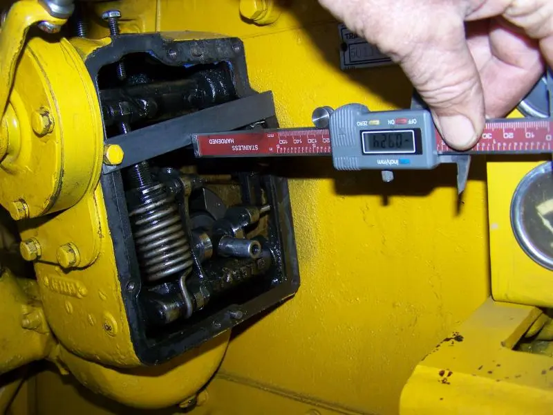
With the 3H Gauge, it has a Zero point set into it when the Lines on the rack and the 3H gauge are lined up when the gauge is installed.
The problem you are encountering is that you cannot determine the Zero starting point for your Full Rack Travel Measurement.
Where you are measuring on the end of the rack, IS reading the direct rack travel as does the 3H gauge BUT, you have no definitive START/ZERO point to start your measuring from--if this makes sense. The OLD Gauge or the 3H gauge does give a definitive start or Zero point.
The 3H gauge and any other gauge that Cat use for rack setting on any engines from this time on--introduction of the 3H gauge--always require the rack to be ZEROED to set what ever rack reading instrumentation being used to a Zero start point.
I am not sure if with the lines lined up straight across, as in OM's pic, is accurate enough to go by for a Zero start point. With one pump unit out you could experiment with getting an accurate centered position of the rack timing line in the pump aperture as a Zero Start point. From experience I have found that "most" rack positions for Low Idle are negative rack readings, hence maybe why you have an excessive apparant rack travel reading when measuring direct on the rack.
Maybe remove one pump unit and check if the lines are "Timed" correctly. If they are not and are set a tooth out you will get low or high power from a standard rack setting but you would likely not be able to shut the unit off or who knows what with the plunger quadrant gear tooth/rack line timing out.
I guess some trial and error is needed here to try and determine a Zero start point and go from there.
Keep at it and we will see if we can help further and try to keep it simple for you to follow.
Once you determine that the pump plungers are timed to the rack correctly then you could remove shims from under the Torque spring group--not the ones between the spring and the thick spacer bar but the ones between to spacer bar and the gov. housing and see if you get some more power. The shims between the torque spring (torque spring spacers) are what allows the engine to increase torque by an increase in rack as the engine speed drops below full load speed as load comes on the system. The torque spring deflects and gives more fuel ( torque rise) for the engine to recover and not tend to stall--
Hope I am helping and not confusing you too much but this is why Cat, and other manufacturers, do not want people playing around will nilly in their fuel systems and give the company and its product a bad name.
A true zeroed actual rack setting to try would be for 1500 Rpm FL and 1640 HI would be 0.275" giving 40hp with fan. You said else where that you were going to change your gen drive ratio ?
It is better I think to keep to one post as we can refer back easier to what we have spoken of and tried before. Hence I am guessing to your rpm change above.
Cheers,
Eddie B.
I was going to change ratio to 1:1, but decided, after studying the rack settings, to fiddle with the rack first. And, you and O.M. have made the problem of zero quite evident. If I could determine the rack position for zero, I could mill a gauge to straddle a pump stem and square on the rack, and match a mark with a timing mark. That would get me repeatable results, but where to put that mark?
I checked the pump/rack timing first thing. There is a scribed tooth on the pump which is visible through the side plate, makes it pretty easy to set the pumps in.
First time I get a chance I'll go to the Cat dealer, hat in hand, and beg them to look for a rack gauge. The area dealership experienced a death, several retirements, an incapacitated man, and the sale of the whole set of stores to another dealer. I find that I know very few people in that organization at this time, but the new owners are a very well respected outfit.
Thanks Ed and Old Magnet
Hi Jack,
if you can eyeball the 3H gauge then all will become evident as to the Zero Position being as OM's pix show with the lines straight across.
The 3H gauge is simply a Vernier type affair, scans below for opertion of the said gauge will give you an idea of what you should be asking the Dealer for and what it looks like.
Cheers,
Eddie B.
As far as I remember, rack zero position is with the rack 'dead centre' hence the reason for graduations both sides of centre on the vernier gauge, if you check the readings found against estimated centre position you may find they make more sense. I have yet to work out a way of finding rack centre or 'zero' without the correct service tools.
Hi Team,
catsilver is correct in that the two sets of graduations, one either side of zero, is that, one set is for positive rack settings and the other is for negative rack settings.
Finding the true center--zero--point is the dilemma here, as catsilver said.
Negative rack settings usually come about as engines are derated for high altitude operation, or even lower HP due to running at lower Full Load RPM's , usually Industrial applications--remember we spoke about Brake Mean Effective cylinder Pressure ( BMEP)ie, average cylinder pressure as averaged over the four strokes of the engine at Full Load. More rpm's allow for more fuel to be injected but still achieve the same BMEP as per the formula :-
BMEP = 792,000 x BHP load Divided by Cubic Inch Displacemnt x RPM
The D311 is 252 cub inch
Rack settings for each engine can be determined if the designed BMEP is known, also more commonly if the (BSFC) Brake Specific Fuel Consumption is known.
Alas, I have BSFC data for some engines of this era but not the D2 U series. Nearest is the 50 HP 933 from that I would estimate that the maximum BSFC for the 42HP D2-D311- at 1525 Rpm Full Load could be around 0.430 to 0.440 lbs per Hp Hour when the rack is set to 0.365"
The above is maybe another way to see if you are getting near designed Hp at Full Load for your engine without breaking it. We often used to Dyno test engines at The Dealer and record the BSFC figure with a fuel flow meter to double check/determine the rack setting of rebuilt engines or re-rated engines.
Cheers,
Eddie B.
Hi Jack,
Even with the 3H gauge you can be fooled if meddlers have been in there. Those quadrant gears on the pumps are just a clamp on installation that can be rotated if the clamp screw is loose or someone has taken it apart. I have not seen any info on how to re-index the plungers and had a heck of a time eyeballing the setting compared to a good pump. I assume there is some type of indexing tooling to set this up but unknown to me. edb, can you shed any light on this task?
Hi OM,
the indexing is done at The Factory on Cat injection pumps and there is no Cat approved method of adjusting them.
They are set up on the Cat Factory calibration test benches and adjusted to give a predetermined delivery volume per 100 shots/deliveries.
This sort of adjustment is done on Bosch pumps all the time to balance the deliveries in a pump group.
Cat say if the delivery for one pump is out it should be replaced ( this is in line with the Cat design criteria of making it easy for anyone to fit a new injection pump element and not have to adjust it in the field. As we know it works well)
I have never tried to adjust one on the Test Bench at The Dealer. I have found a new one that was out and it was replaced under warranty--this would be a rare event.
For the same reason the plunger from one pump element should not be swapped with another as they are hand selective fitted to each barrel by virtue of the component +/- machining tolerances to give the minimum safe working clearance.
Hope this helps.
Cheers,
Eddie B.


Our channel highlights machines from the earliest Holt and Best track-type tractors, equipment from the start of Caterpillar in 1925, up to units built in the mid-1960s.
Chapter Fifteen
| Placerville, CAChapter Nineteen
| 1234 Carngham-Lake Goldsmith Rd, Lake Goldsmith, Victoria, 3373, AustraliaChapter Two
| Stradsett, Nr Downham Market. Norfolk PE33 9HA UKChapter Two
| Faulkner Farm, West Drove, Wisbech, Cambridgeshire, PE14 7DP, UK
Antique Caterpillar
Machinery Owners Club
1115 Madison St NE # 1117
Salem, OR 97301
Terms & Privacy
Website developed by
AdCo
"I became a member recently because the wealth of knowledge here is priceless."
-Chris R