Ryan, take the 4 bolts out of cyl flange. Force the idler forward and hold it securely. Don't want it coming back on your hand. Use a pair of channel locks to pull piston forward and out of cylinder. If you can't get it out take off snapring and just change seal with piston in place.
Later Bob
Hope that works for you as step 2, after splitting the track, is the choice of either removing the entire recoil spring assembly or the carrier roller support assembly to get clearance to remove the piston or piston/cylinder assembly according to the service manual. No mention of resealing in place but can't see any reason why not if you can access both sealing rings.
I always split the track and unbolted the carrier roller support to do the adjuster seal. There's not that much extra work to do that, and you always find lots of other things that need attention while you're in there .. 😄
Check the idler yoke pushrod for bends. They are prone to bending and creating misalignment of the idler. Also, the wear pads on the end of the equalizer bar probably need some build up with weld. In addition, 9 times out of 10, those carrier support bolts are either broken, or loose, or have had the spring washers bust up and fall out, making the carrier support bounce around.
I always chucked the spring washer idea and just used Cat hardened washers, under the carrier roller support bolt heads. Torque them up to proper torque and you never have any more problems with spring washers breaking up, and making the carrier support jump around.
The book shows either taking the carier roller assembly off or the recoil assembly. Definatley don't want to have to take the recoil assembly out if I can help it. Only bad thing about taking the carier roller assembly off is the old rusted in bolts, might be a couple of welds around it too. Can't remember right off the top of my head.
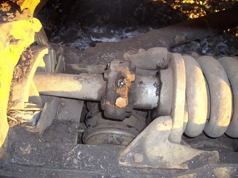
Things don't look quite straight in there either, when you look down from above the push rod is not quite straight with the rollers. I didn't want to look to hard in fear of finding somethign else brocken or bent though.lol.. I'll take a closer look this morning once the sun comes out and maybe get a pic of it.
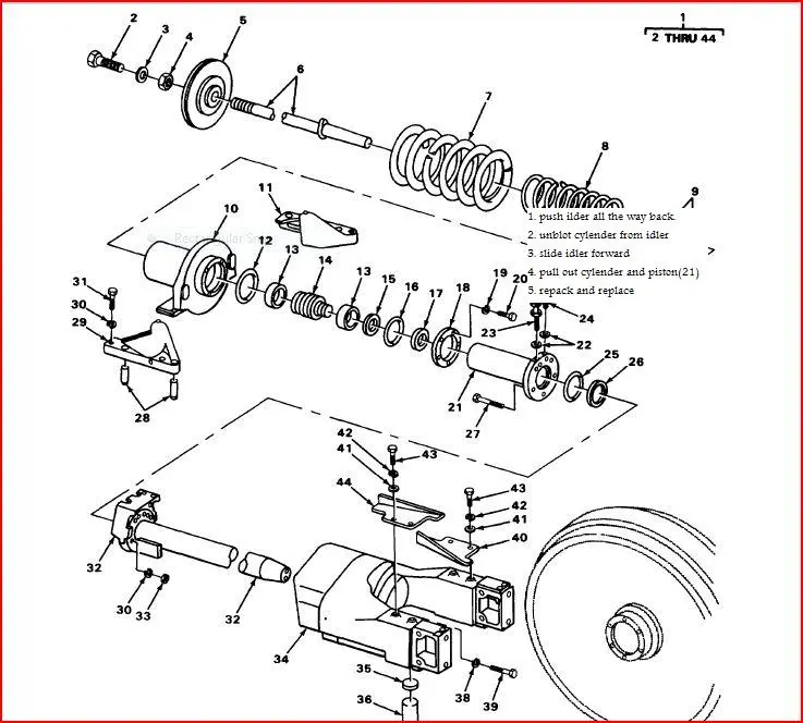
Where abouts is the snap ring Bob? The parts diagram isn't showing me that. Ther's a retaining ring piston seal number 16 Also there's a seal at the back where the cylender slides in towards the recoil spring, that's where it seems to be leakign out around. Item number 12 in the parts diagram. They call it a packing preformed pilot Is that just a seal to keep the dirt out? The grease is coming back out towards the cylender. Are the only seals that I would need to replace on the piston it's self or just infront and behind it? Looks like there's others that I may as well replace while I'm in there if I can get to them.
Sorry for be so long winded and confusing but I'm just trying to get this straightend out. I suspect once I start tearing it apart it will be more clear to me as I've never really worked much on crawlers. I'm only 24 yet so not much life experience with these machines. I've got my eye on a second crawler now though. It's a D7 17A. Don't konw the year yet but it looks to be in real good shape except for the rails that apear to be pretty well stretched out. I haven't seen it yet and I've only seen a picture of it from one side but it looks promising. Doesn't come up for acution though till next june.
Ryan
Ryan, any I have had apart had a snap ring on the front of part#14 holding the piston seal on. If you can get the yoke flange off of the cyl flange and pry cyl back the front of the piston will be visable. Wipe off grease and see what holds the seal in place. All I have seen had a snapring that wraps around 2 times and will come off with a pick or small screwdriver. Look for dammage to cup seal. Cnange seal and two rings in face of cyl flange. If the cup seal looks good you might have a bad cyl. If so you need to do work OZ says.
Later Bob
Hard to find a good detail on the adjuster.....this should cover it.
Yes, only one seal, accessible as Bob describes.
Okay, parts diagrams aren't always the greatest but sure do help. The diagram I have is off of a Millitary D7E but I'm fairly certain that they're the same anyways. Has to be something there to hold it in place though like you say. Thanks
Here's a picture of the adjuster.
Skidder should be coming out of the shop tonight. Have to do a oil change on the one truck and then hopefully get the cat in the shop to work on it.
Still contemplating that block heater too. There's one plug in one of the inspection covers just above the starter but I don't supose that will get me into the water jacket at all. Everything is so closed in that it's hard to see where the plugs are in the front of the block or water pump.
Thanks
Ryan
Is that a factory installed direct electric start?
If it was originally pony start there should be two connections on that cover plate. One would be the pony cooling water supply and may have a block off plate installed if it is a conversion. The other small one is the block drain. A factory direct may not have the pony connection.
The water pump inlet connections would best be accessed from below....not good if you have a belly pan.
Checked a later model service manual source and found different instructions. (47A3396-up and 48A6393-up)
On these units you do not have to remove the recoil assembly or the carrier support assembly to get the adjuster out.
1. Split track
2. Remove front idler
3. Remove bolts and nuts from front end of idler recoil rod (5 ea)
4. Strike recoil rod with hammer at the rear of yoke to unseat the taper fit in yoke.
5. Slide yoke forward on track frame. Turn recoil rod 180 degrees and move it forward to obtain clearance to remove cylinder.
With the cylinder out you can change the seal (behind the 5-bolt ring) on the spring side of the cylinder flange.


Our channel highlights machines from the earliest Holt and Best track-type tractors, equipment from the start of Caterpillar in 1925, up to units built in the mid-1960s.
Chapter Fifteen
| Historic Santa Margarita Ranch, 20000 El Camino Real, Santa Margarita, CA 93453, USAChapter Thirty
| Hartley - South AustraliaChapter Two
| Newby Hall, Ripon, Noth Yorkshire, HG4 5AJChapter Two
| Freshfield Farm, Sloop Lane, Scaynes Hill RH17 7NP UK
Antique Caterpillar
Machinery Owners Club
1115 Madison St NE # 1117
Salem, OR 97301
Terms & Privacy
Website developed by
AdCo
"I became a member recently because the wealth of knowledge here is priceless."
-Chris R