ACMOC
Login
ACMOC
D6D sleeve meter pump

D6D sleeve meter pump

Showing 1 to 10 of 14 results
1
Richard~J~W
Topic Author
Offline
Send a private message to Richard~J~W
Posts: 389
Thank you received: 0
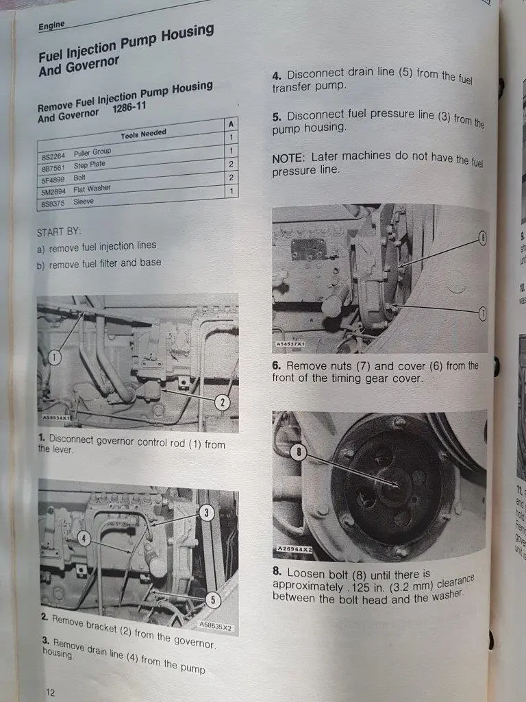
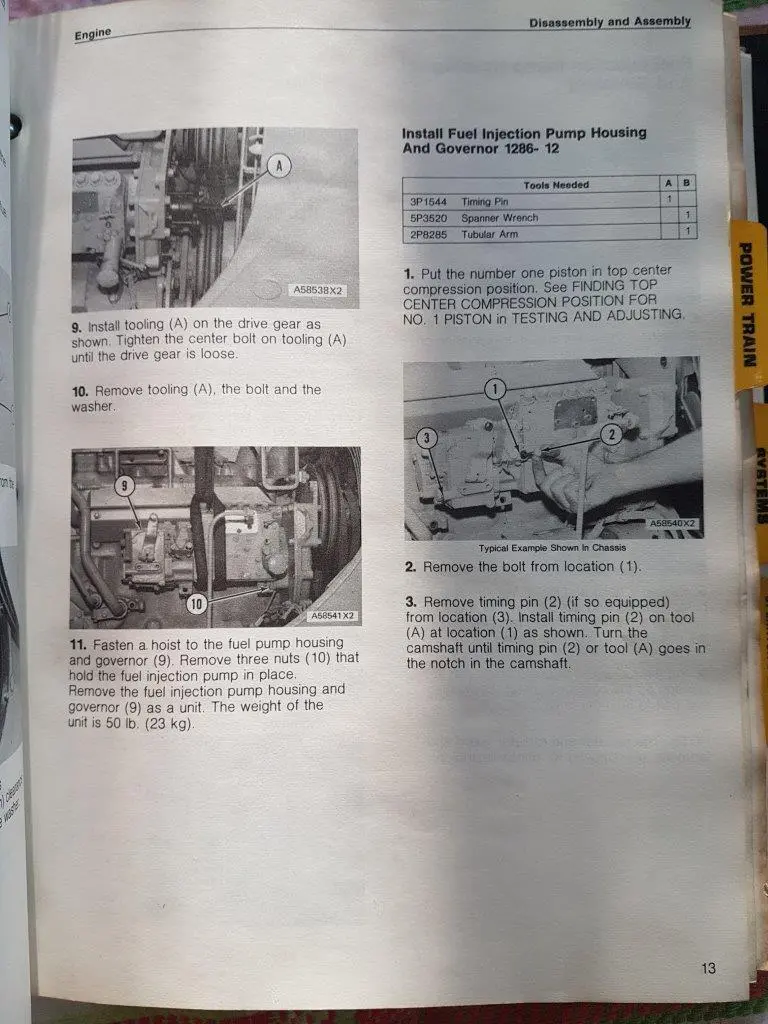
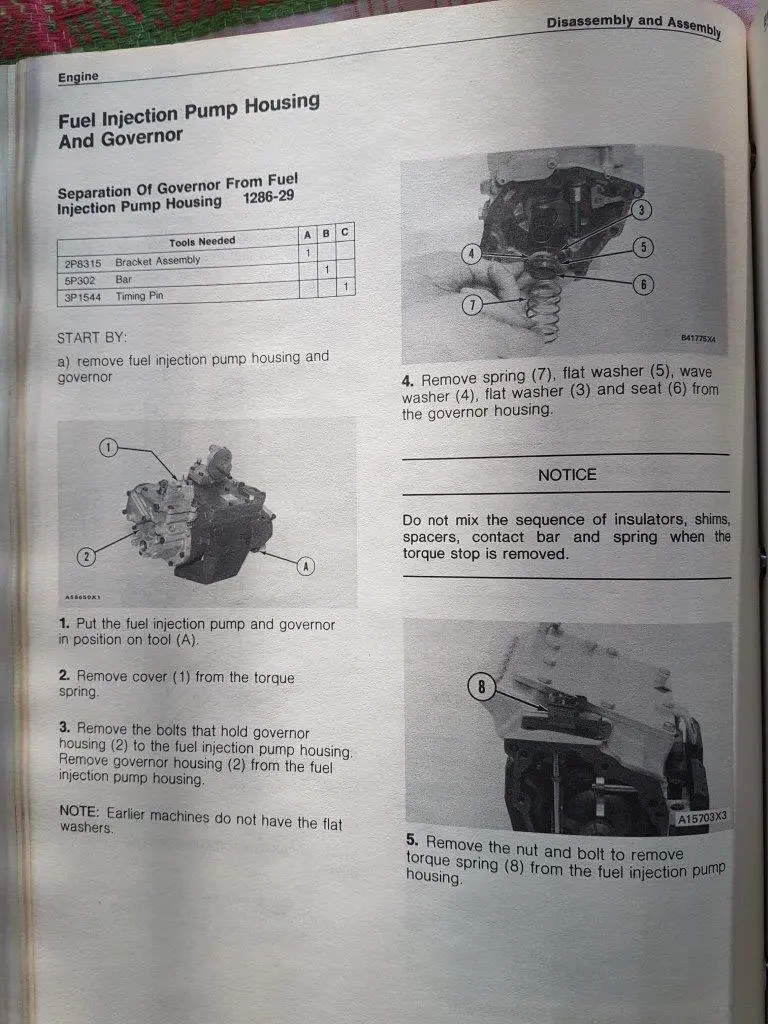
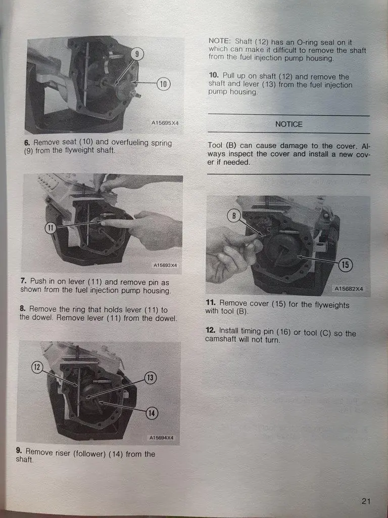
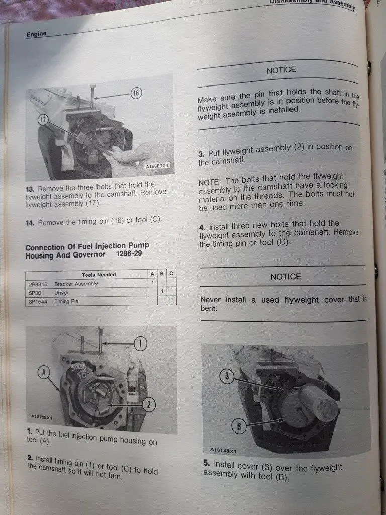
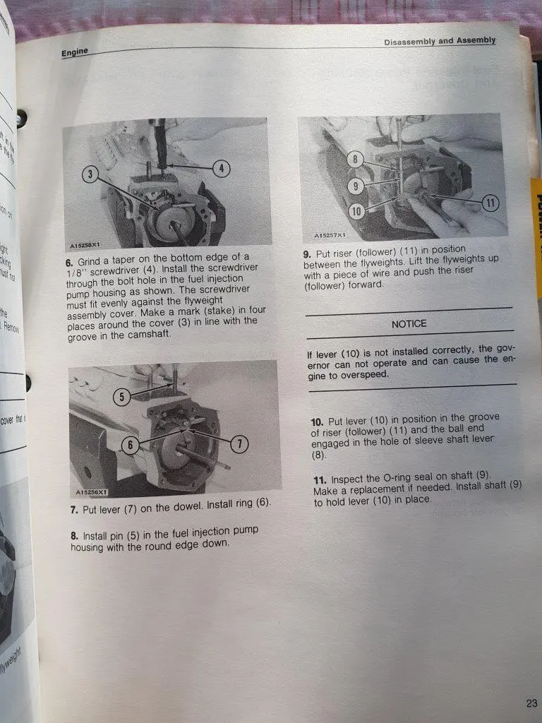
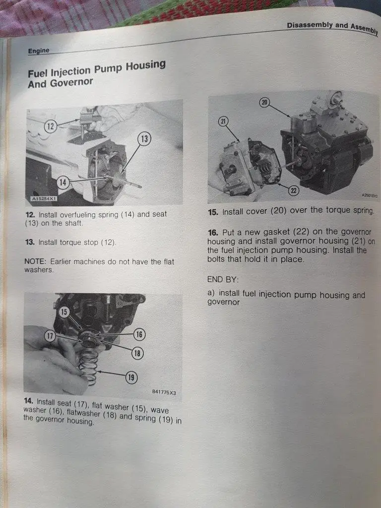
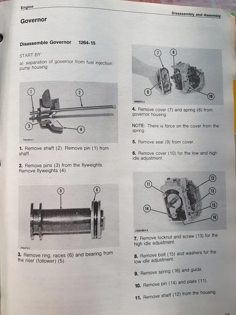
Can you fellas advise me on this fuel pump, I am putting new seals in the throttle shaft so disassembled it.

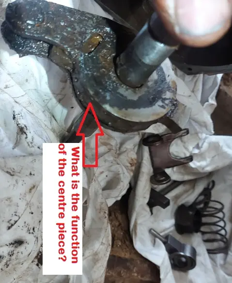
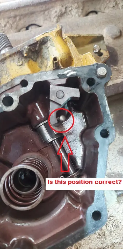
Pic 1: are the parts correctly located?

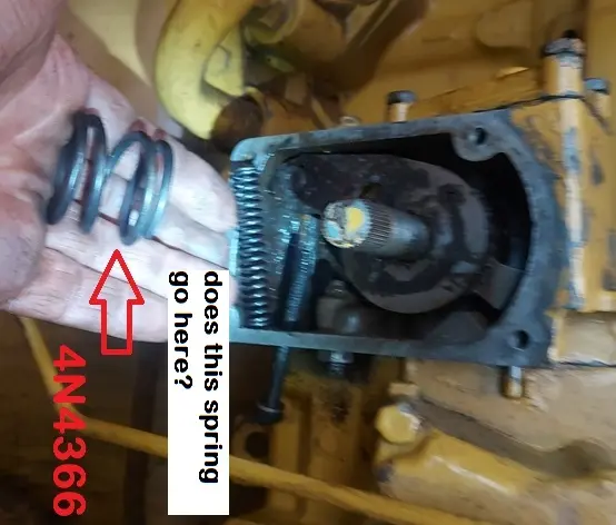
pic 2: we have a spring part no. 4N4366 - where does it go? don't find it in the parts book

pic 3: Inside the cavity where the throttle shaft enters there's the high speed screww plus another with a spring on......how do I get the adjustment on the screw/spring correct and what is the function of it because it seems to free float on against the middle part

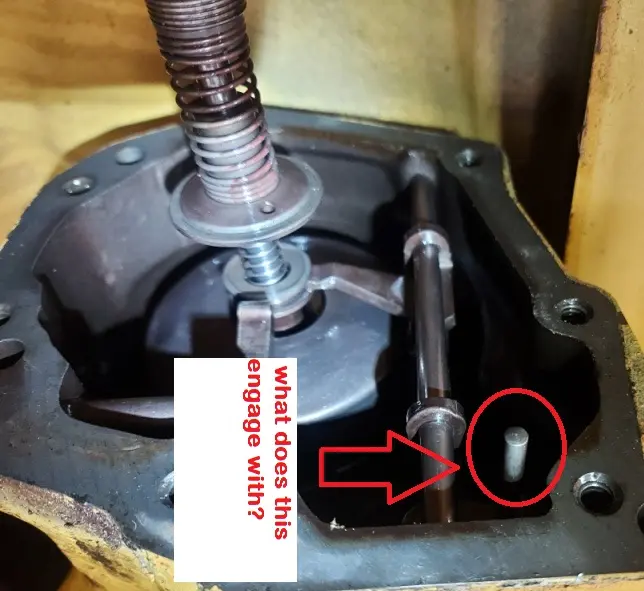
pic 4: In the top corner of the pump there's a small shaft sticking out, seems like it connects with something in pic 1....what does it do?
Attachment
Attachment
Attachment
Attachment
Please log in or create an account to join the conversation.
Thu, Oct 7, 2021 2:15 AM
edb
Offline
Member
Send a private message to edb
Posts: 4,027
Thank you received: 0
Hi Richard,
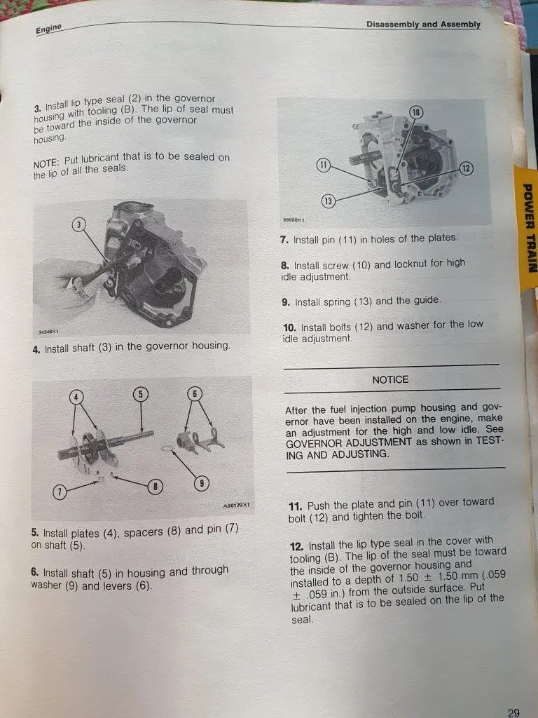
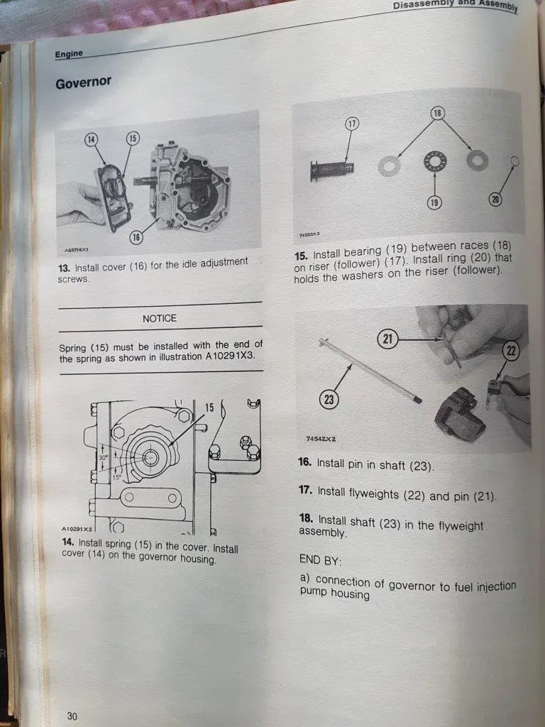
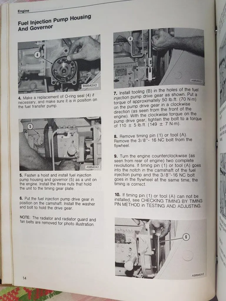
Not sure if the PDF will attach--it has details of assembly etc. for a 3304 engine--3306 is same but 2 extra pump elements.Been some 20 years or more since I worked on these so will try and answer your queries.If this does not help please ask again.

Pic 1,
the centre piece is the shutoff detent and works in conjunction with the low idle and high idle stop screws--with the spring pressure the two side plates crush against the slug on the centre piece--the slug works in the groove for normal operation and is forced back between the plates in the stop position--it gives the detent stop feel.

Pic 2,
the springs shown are correctly orientated for position.

Pic 3
,the pin is in its correct location when that lever with the pin is engaged to the slot in the control shaft, the pin and the other double end lever is to limit the rack opening as dictated by the Air Fuel Ratio control cylinder and its setting.

Pic 4,
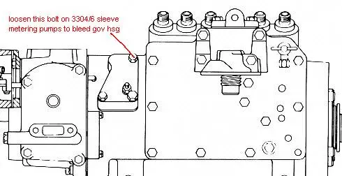
cannot recall but I think it is the end of the Fuel rack which has a lever and pin on that end from memory and as seen in the PDF which should assist you in sorting it out when you view the pictures over several pages. It looks odd because the levers act on the pin and so it does not seem to be connected to anything but it works when everything is aligned correctly.These are complicated but if anything is wrong ti usually does not assemble --do not force anything and go back and recheck until it slides together easily. One could say they are a bit smoke and mirrors type magic in operation.Also attached is how to bleed air from the Governor Housing or you will crank for ages to get the fuel level to rise in the main housing for the injection pumps to pick up--fuel sits at a low level in both housings and must be compressed by the fuel transfer pump pressure to raise the fuel level to run.Hope this helps.
Cheers,
Eddie B.

EDIT,  looks like the PDF is too big to attach--I have tried copying pages from it so far without success--Sorry--this data should be in the Library here.

Have added some scans I saved from someone's post in the past alas one is too small and blurry to read.
Attachment
Attachment
Attachment
Attachment
Attachment
Attachment
Attachment
Attachment
Attachment
Attachment
Attachment
Attachment
Attachment
Please log in or create an account to join the conversation.
Thu, Oct 7, 2021 8:09 AM
edb
Offline
Member
Send a private message to edb
Posts: 4,027
Thank you received: 0
https://www.google.com/url?sa=t&rct=j&q=&esrc=s&source=web&cd=&cad=rja&uact=8&ved=2ahUKEwiq2_TPxLfzAhXacn0KHcePD7oQFnoECAIQAQ&url=https%3A%2F%2Fbarringtondieselclub.co.za%2Fcaterpillar%2F920-930%2Freg00501-01%2Fsystem-operation-testing-and-adjusting-3304-vehicular-engine.pdf&usg=AOvVaw27RQ7GLnetQsxZDvFH7dqB

Hi,
hoping this link works---3306 is the same except for the 2 extra injection pumps.
Cheers,
Eddie B.
Please log in or create an account to join the conversation.
Thu, Oct 7, 2021 12:18 PM
Richard~J~W
Topic Author
Offline
Send a private message to Richard~J~W
Posts: 389
Thank you received: 0
Reply to edb:
https://www.google.com/url?sa=t&rct=j&q=&esrc=s&source=web&cd=&cad=rja&uact=8&ved=2ahUKEwiq2_TPxLfzAhXacn0KHcePD7oQFnoECAIQAQ&url=https%3A%2F%2Fbarringtondieselclub.co.za%2Fcaterpillar%2F920-930%2Freg00501-01%2Fsystem-operation-testing-and-adjusting-3304-vehicular-engine.pdf&usg=AOvVaw27RQ7GLnetQsxZDvFH7dqB

Hi,
hoping this link works---3306 is the same except for the 2 extra injection pumps.
Cheers,
Eddie B.
Eddie,

A huge thank-you to you for posting the information and detailed answers.......it is greatly appreciated!

best regards
Richard
Please log in or create an account to join the conversation.
Thu, Oct 7, 2021 11:49 PM
gauntjoh
Offline
Member
Moderator
Librarian
Admin
Chapter Two
Send a private message to gauntjoh
Posts: 1,153
Thank you received: 1
Reply to Richard~J~W:
Eddie,

A huge thank-you to you for posting the information and detailed answers.......it is greatly appreciated!

best regards
Richard
Hey Richard, I know you travel an awful lot but looks like you're in Australia at the moment  LOL
Please log in or create an account to join the conversation.
Fri, Oct 8, 2021 2:06 AM
Richard~J~W
Topic Author
Offline
Send a private message to Richard~J~W
Posts: 389
Thank you received: 0
Reply to gauntjoh:
Hey Richard, I know you travel an awful lot but looks like you're in Australia at the moment  LOL
It does seem that way sometimes, not knowing if I am on my a$$ or my head 😊
Please log in or create an account to join the conversation.
Sat, Oct 9, 2021 9:26 PM
Richard~J~W
Topic Author
Offline
Send a private message to Richard~J~W
Posts: 389
Thank you received: 0
Reply to Richard~J~W:
It does seem that way sometimes, not knowing if I am on my a$$ or my head 😊
soooo........I am on the reassmbly phase of this now.....and I have it a snag.......I cannot get any diesel out of the injector ports, have bled the governer housing and the main box.
What I have found is the rack seems to have got stuck.
It was nice a free when I put it together, but on strip down looking for a fault it was well and truly stuck in the "off" position, then working it some its come free again.

The question is what causes them to go tight?
Please log in or create an account to join the conversation.
Tue, Nov 30, 2021 2:28 AM
edb
Offline
Member
Send a private message to edb
Posts: 4,027
Thank you received: 0
Reply to Richard~J~W:
soooo........I am on the reassmbly phase of this now.....and I have it a snag.......I cannot get any diesel out of the injector ports, have bled the governer housing and the main box.
What I have found is the rack seems to have got stuck.
It was nice a free when I put it together, but on strip down looking for a fault it was well and truly stuck in the "off" position, then working it some its come free again.

The question is what causes them to go tight?
Hi Richard,
not sure I have come across this in a re-assembled unit--operating the rack/sleeve rod makes the sleeves slide up and down the plungers to pump more or less fuel or further to shut off position.
If all the tricky governor linkages etc. were assembled correctly without forcing anything nothing would have got bent or burred--burrs are an issue with these and basically everything we treated as being burred and so were checked and de-burred as needed.
Maybe the sleeves had some gum on them which solidified after cleaning and reassembly.
Fitting the pump elements back in all the while checking that the sleeves have engaged and stay engaged with their respective levers is tricky without the correct tools to hold and lower the elements into the main pump body bores and then screw the retaining nut in all the while checking the sleeves stay engaged and the barrel seats squarely.
I have seen units where rough handling at this stage can result in broken plungers or burrs on the working surface/s of the lever to sleeve causing tight operation until the burr is worn some to allow easy movement.

Will think on it some more but I am remembering back some nearly 20 years now since I worked on them.

Cheers,
Eddie B.
Please log in or create an account to join the conversation.
Tue, Nov 30, 2021 8:57 AM
Richard~J~W
Topic Author
Offline
Send a private message to Richard~J~W
Posts: 389
Thank you received: 0
Reply to edb:
Hi Richard,
not sure I have come across this in a re-assembled unit--operating the rack/sleeve rod makes the sleeves slide up and down the plungers to pump more or less fuel or further to shut off position.
If all the tricky governor linkages etc. were assembled correctly without forcing anything nothing would have got bent or burred--burrs are an issue with these and basically everything we treated as being burred and so were checked and de-burred as needed.
Maybe the sleeves had some gum on them which solidified after cleaning and reassembly.
Fitting the pump elements back in all the while checking that the sleeves have engaged and stay engaged with their respective levers is tricky without the correct tools to hold and lower the elements into the main pump body bores and then screw the retaining nut in all the while checking the sleeves stay engaged and the barrel seats squarely.
I have seen units where rough handling at this stage can result in broken plungers or burrs on the working surface/s of the lever to sleeve causing tight operation until the burr is worn some to allow easy movement.

Will think on it some more but I am remembering back some nearly 20 years now since I worked on them.

Cheers,
Eddie B.
Thanks Eddie.

We didn't take the plungers out, just pulled the governor housing off to reseal the throttle spindle.

As you say that rack/sleeve rod goes up and down the plungers, what i noticed was that there was some fore-aft movment, but was tight in the up/down plane.....almost as if it was sticking on an injector barrel....but we got it free, it springs up and down nicely now......as it did when I first worked on it. I have reassembled it again less gaskets (they are on order) checking freeplay with every turn of the bolts, still seems ok.....which was how it was last time.
Please log in or create an account to join the conversation.
Tue, Nov 30, 2021 3:29 PM
Richard~J~W
Topic Author
Offline
Send a private message to Richard~J~W
Posts: 389
Thank you received: 0
Reply to Richard~J~W:
Thanks Eddie.

We didn't take the plungers out, just pulled the governor housing off to reseal the throttle spindle.

As you say that rack/sleeve rod goes up and down the plungers, what i noticed was that there was some fore-aft movment, but was tight in the up/down plane.....almost as if it was sticking on an injector barrel....but we got it free, it springs up and down nicely now......as it did when I first worked on it. I have reassembled it again less gaskets (they are on order) checking freeplay with every turn of the bolts, still seems ok.....which was how it was last time.
just to update on today's findings......I was at the machine this morning, as mentioned before its not running, just reassembled less gaskets and stood overnight. Looking in thru the pump side cover aperture and working the lever the up and down movement of the sleeves got progressively stiffer, to the point where moving the stop control to the run position the rack stayed where it was.
Please log in or create an account to join the conversation.
Wed, Dec 1, 2021 1:14 AM
edb
Offline
Member
Send a private message to edb
Posts: 4,027
Thank you received: 0
Reply to Richard~J~W:
just to update on today's findings......I was at the machine this morning, as mentioned before its not running, just reassembled less gaskets and stood overnight. Looking in thru the pump side cover aperture and working the lever the up and down movement of the sleeves got progressively stiffer, to the point where moving the stop control to the run position the rack stayed where it was.
Hi Richard,
sounds like the plungers and sleeves are dry and some loose juice should help lubricate them--make sure it is a clean fluid and not decanted stuff as the fine dust settling in there could be the issue or moist ambient air could start corrosion too.
It should be remembered that these units have the injection pumps running in diesel fuel and this lubricates them and helps prevent corrosion issues when water free fuel is used.

From memory I believe we were told that Japanese engineers came up with this Sleeve Metering design that worked well with their fuels of the day but I suspect was less so else where.
Cat would say they addressed the issue by re-fitting a later version of the previous Compact pumps which they called Interim Scroll this then led to the next generation of Injection Pumps which  they called New Scroll.
Cheers,
Eddie B.
Please log in or create an account to join the conversation.
Wed, Dec 1, 2021 8:59 AM
Showing 1 to 10 of 14 results
1
YouTube Video Placeholder

Follow Us on Social Media

Our channel highlights machines from the earliest Holt and Best track-type tractors, equipment from the start of Caterpillar in 1925, up to units built in the mid-1960s.

Upcoming Events

CAFES 2025 TULARE, CALIFORNIA

Chapter Fifteen

| Tulare, California

Wheatlands Warracknabeal Easter Rally

Chapter Nineteen

| 34 Henty Hwy, Warracknabeal

Veerkamp Open House 2025

Chapter Fifteen

| Placerville, CA

Stradsett Park Vintage Rally

Chapter Two

| Stradsett, Nr Downham Market. Norfolk PE33 9HA UK
View Calendar
ACMOC

Antique Caterpillar
Machinery Owners Club

1115 Madison St NE # 1117
Salem, OR 97301

[email protected]

Terms & Privacy
Website developed by AdCo

Testimonials

"I became a member recently because the wealth of knowledge here is priceless." 
-Chris R

Join Today!