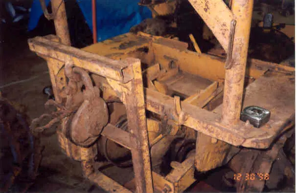
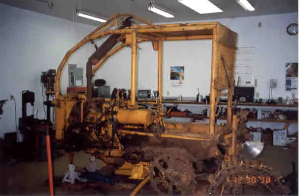
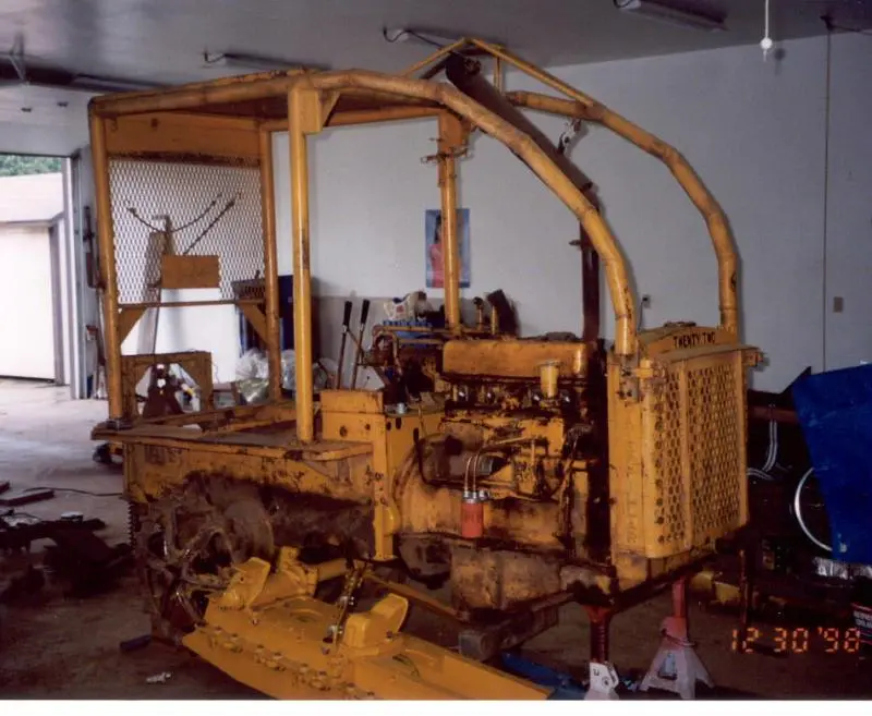
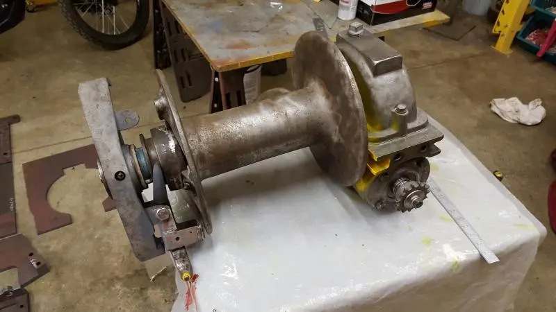
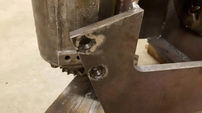
These are old pictures now, but you see how it was mounted. I spent many hours on that cat tugging out logs!
[attachment=38340]catleft.jpg[/attachment][attachment=38341]catright large.jpg[/attachment]
Hi Dan,
I'd like to see the finished product.
I also have a winch for my Twenty Two.
Just haven't gotten to it yet. Hyster/Willamette I believe
I like your thoughtful approach Dan 👍 It looks like the PTO will still be usable with the winch in place, but I'm sure I'm mistaken?
Scott,
I would like to see your winch setup too. Did you already post pictures?
Neil, the PTO is not useable for anything but the winch. I never used it anyway, and I have a JD tractor loader for pto work anyway.
I really miss having a winch since I live in a semi wooded are and often have trees to pull down or out. I like to get the stumps out if I can and the winch makes that possible for such a light Cat.
Someday I will finish my D2 restore and I have a D2N for it. That is a few years off I believe.
Hi Dan,
No I never posted any pictures. It's in storage at a friends right now
It'll be a while before I can
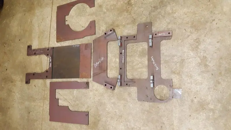
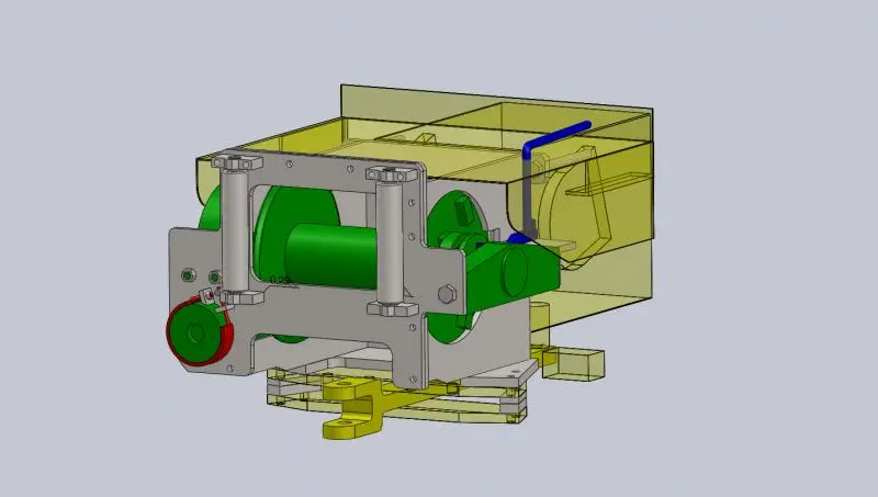
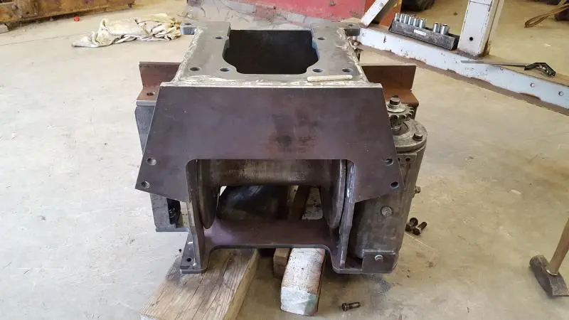
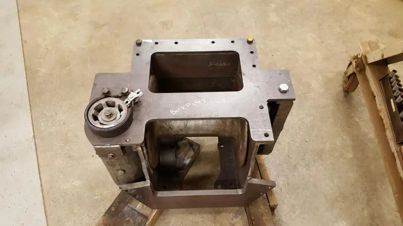
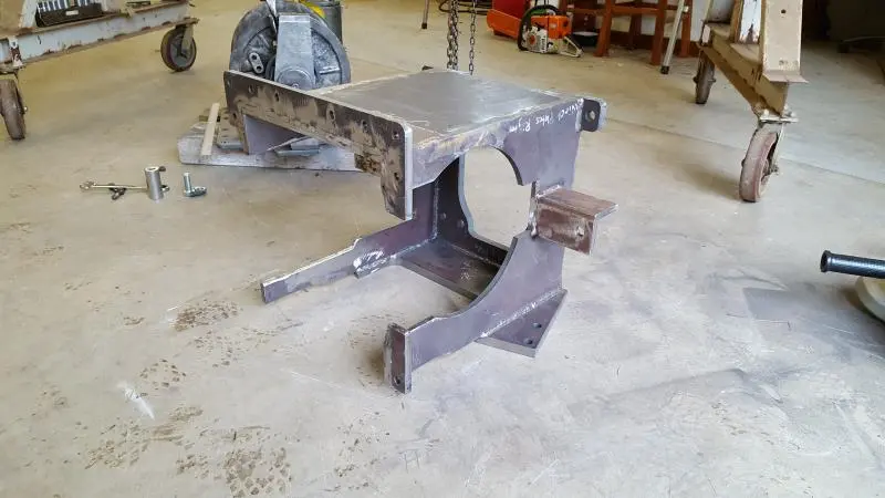
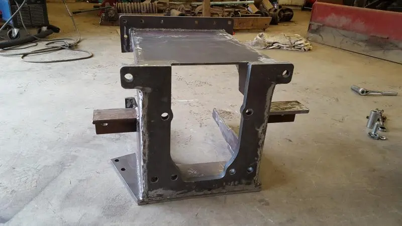
Picked up the plates from the metal supplier yesterday. All is looking good except the side plates with the bigger cuts ended up a little warped. I think I can easily straighten them with a sledge hammer.
[attachment=38406]20161021_073248.jpg[/attachment]
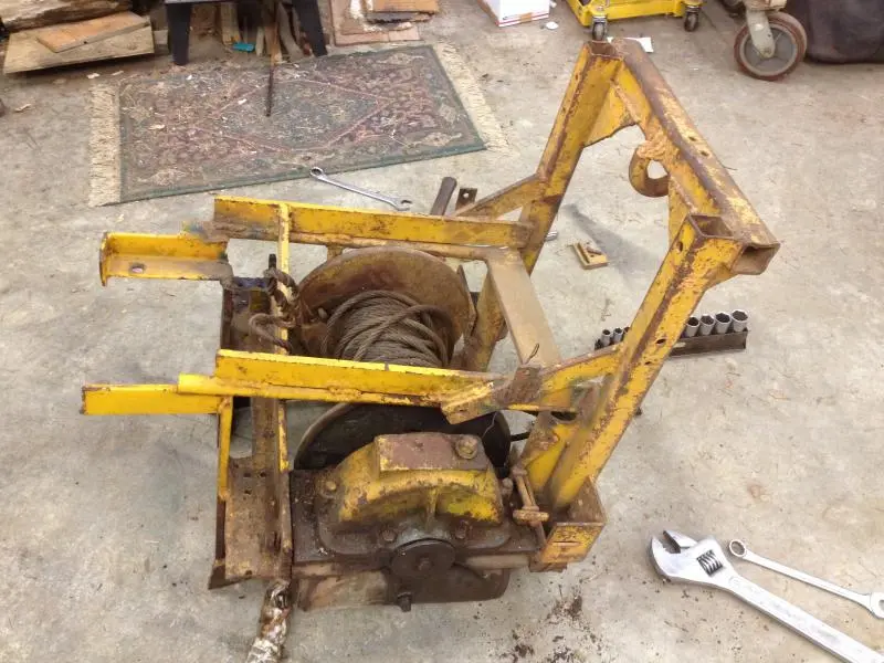
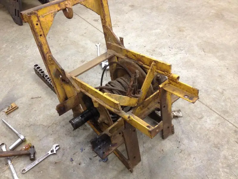
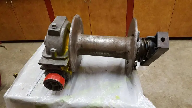
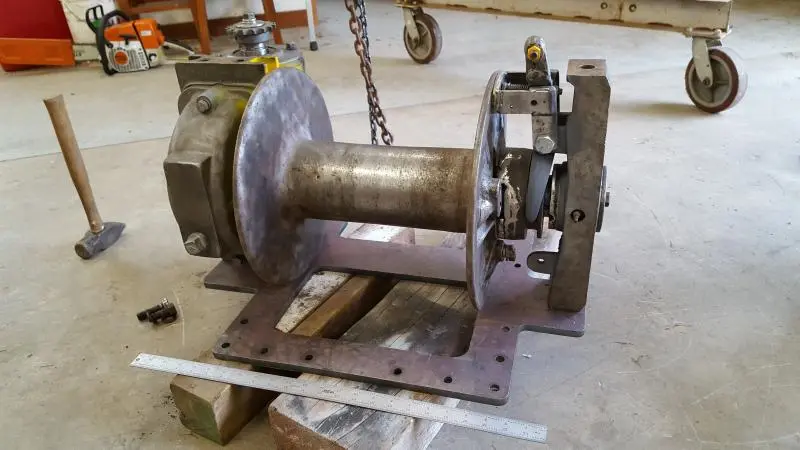
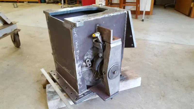
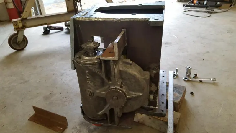
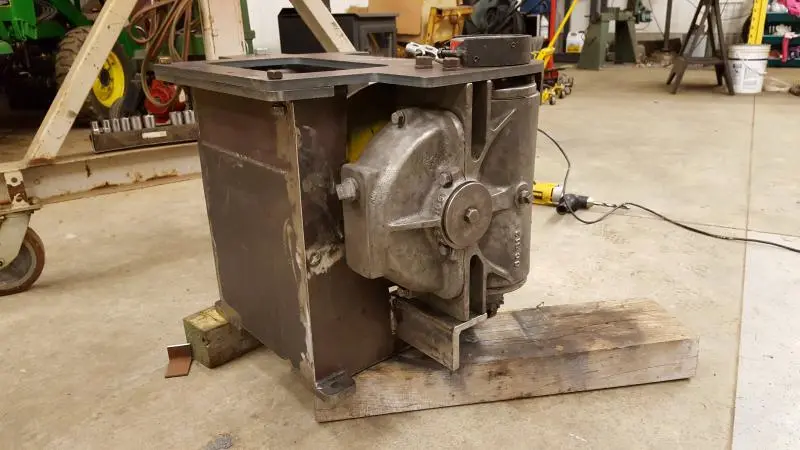
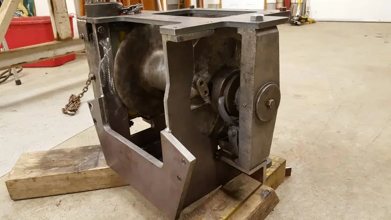
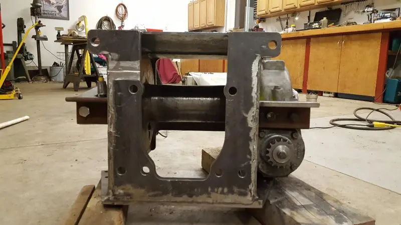
I added a couple of shots of the rebuilt winch. Cleaned and ready for primer. I am going to prime it before welding up the mount so the spatter is less likely to stick to the bare metal. One mess I want to avoid cleaning up.
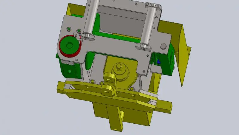
[attachment=38404]20161021_073306.jpg[/attachment][attachment=38405]20161021_073314_001.jpg[/attachment]
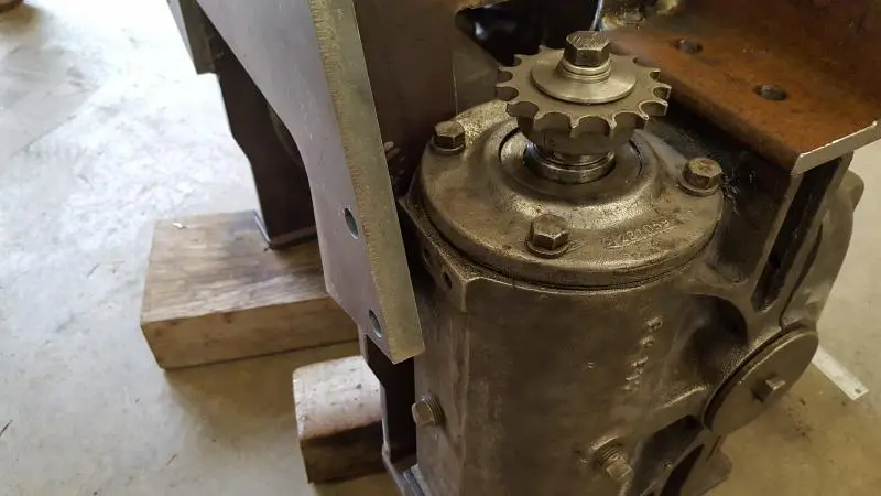
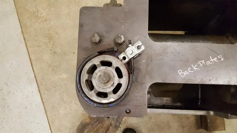
I picked up the rollers and the angle iron metal 'ears' that hold the front of the winch castings. Bushings for the rollers also came today.
We will see how far I get this weekend with the welding.
wow looking good i too have a PTO winch i would like to install on My D2J3 as i got a logging arch for it plus it's always better too have a winch than not and have not had luck with getting a D2N winch i guess there was not much call for them on the flat ground. this may be a dumb question but are you only running power in ? or how are you reversing the winch with the PTO or you just free wheeling out? would it there be any damage if the PTO trued backwards say if you where to let off on the winch and still had a load on the line or are you just relying on the worm gear to stop that from happening? take lost of Photos as i will to watching very closely to this neat project. i like a cat with a winch on it cus that means that the seat like you said will be raised giving me a little more leg room as i 6'3" keep up the good work.
nice project!!
i am interesting in the steps till its finished!
its driven by chain from the pto from the tractor? tractor has a handle in front of seat for pto to switch on ?
and i see a clutch so you can clutch it out to winch out and under power winch in?
Hi Mog,
This winch is power in only, and free spool out. No reverse capability.
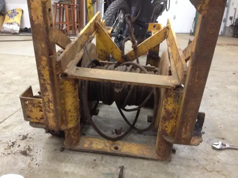
There is a brake band not installed that keeps it from spooling out. It will hold mostly but it can spin out. I will show the brake setup after it is installed.
MARCOTEN,
It is chain drive from the pto shaft. The control is the standard PTO lever. When there is no tension, the release pops right out. You cannot release cable tension by the clutch with this winch.


Our channel highlights machines from the earliest Holt and Best track-type tractors, equipment from the start of Caterpillar in 1925, up to units built in the mid-1960s.
Chapter Nineteen
| 1234 Carngham-Lake Goldsmith Rd, Lake Goldsmith, Victoria, 3373, AustraliaChapter Two
| Stradsett, Nr Downham Market. Norfolk PE33 9HA UKChapter Two
| Faulkner Farm, West Drove, Wisbech, Cambridgeshire, PE14 7DP, UKChapter Nineteen
| Cnr Hiller Lane and Ballarat Road, Hamilton, Vic, 3300
Antique Caterpillar
Machinery Owners Club
1115 Madison St NE # 1117
Salem, OR 97301
Terms & Privacy
Website developed by
AdCo
"I became a member recently because the wealth of knowledge here is priceless."
-Chris R
