
-
Forum
-
Antique Caterpillar Machinery Owners Club
-
DISCUSSION
-
Power Tilt Conversion
Less
More
-
Posts: 2778
-
Thank you received: 77
-
9 years 5 months ago #125997
by dpendzic
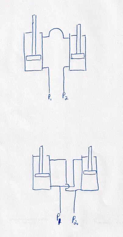
Pete--i'm thinking back to my hydraulics courses in college---force equals pressure times area--when p1 is pressurized it pushes against the piston in that cylinder thus extending the rod. the oil trapped in the rod end is then pressurized and then escapes thru the hose to the other rod end of the other cylinder although due to different areas it will be somewhat less than p1. the second rod end sees a force from this pressure and pushes the rod to retract exerting a force on the blade to tilt it down. since liquids cannot be compressed what comes out of one cylinder has to go into the other cylinder---it would be interesting to see what the pressure is on the rod ends as compared to p1
when we set up hydraulic jack systems for pile load tests---some being six 100 ton jacks--we just used one common feed and each jacks movement was dependent on steel bending and crushing--but we were certain we had the same pressure/force on each one.
Maybe this is just a case of east coast,west coast,south Africa semantics??
D2, D3, D4, D6, 941B, Cat 15
Hancock Ma and Moriches NY
Please Log in or Create an account to join the conversation.
Less
More
-
Posts: 2533
-
Thank you received: 1
-
9 years 5 months ago #126000
by Garlic Pete
dependzic - I agree, I think we're saying the same thing. As you said, East Coast, West Coast, South Africa, then you throw in Garlic speak and it is a wonder we communicate at all!
My understanding of the theory is the same as you, the force exerted by the fluid on the pistons is constant across the entire system. I think the piece you're missing is that in glum's system, only one side of each piston is being acted upon by the pump. Activation of Glum's system causes the pump to push one piston down, which pushes fluid through the bridge line into the back side of the other piston, which pushes fluid out toward the pump (or looked at another way, from which the pump suck fluid).
In a system with both rods plumbed to the pump and reservoir, the pressure exerted by the pump (whether sucking or blowing) is applied to four sides of the two pistons, the front side and the back side. This means that in this type of system, the same pump pressure will result in twice the force exerted upon the two piston rods. In this system, essentially, the pistons on both rods are both pushed upon and sucked upon by the pump.
I'm sure my explanation isn't really theoretically correct, but that is how I think about it anyway.
Pete.
Please Log in or Create an account to join the conversation.
Less
More
-
Posts: 968
-
Thank you received: 6
-
9 years 5 months ago #126004
by cojhl2
Well apparently I'm lost (what's new).
Glum's top drawing is very different than his bottom one. The top one defines the "dead side" hookup alluded to earlier. The way I see it Glum has it hooked up as per the lower schematic. And that would be correct.
Pressurize P1 the left cyl extends, the right cyl retracts (with not quite the force exerted by the left) but nevertheless helps move the blade. When P1 is pressurized P2 is unloading to the reservoir.
It isn't more complicated than this is it?
I don't think the top schematic is at all workable.
9U(2), 5J, IHC544, Ford860
Please Log in or Create an account to join the conversation.
Less
More
-
Posts: 2533
-
Thank you received: 1
-
9 years 5 months ago #126006
by Garlic Pete
cojhl - I understood glum's plumbing was as in the top drawing, which is why it only exerts half the force that the same setup would under the bottom drawing.
Glum's setup can't extend or retract both cylinders at the same time. When one rod goes out, it pushed the fluid through the connection at the top of the drawing to push the other rod in and vice versa.
As long as the reduced force isn't an issue and the air purging concerns mentioned by catsilver are addressed, the top drawing is simpler as it only requires one valve and one set of connections to the rods.
Pete.
Please Log in or Create an account to join the conversation.
Less
More
-
Posts: 2473
-
Thank you received: 2
-
9 years 5 months ago #126008
by STEPHEN
Well apparently I'm lost (what's new).
Glum's top drawing is very different than his bottom one. The top one defines the "dead side" hookup alluded to earlier. The way I see it Glum has it hooked up as per the lower schematic. And that would be correct.
Pressurize P1 the left cyl extends, the right cyl retracts (with not quite the force exerted by the left) but nevertheless helps move the blade. When P1 is pressurized P2 is unloading to the reservoir.
It isn't more complicated than this is it?
I don't think the top schematic is at all workable.
If it was hooked like the lower drawing, the blade would not hold tilt against a load with the control in neutral because both ends of opposite cylinders are free to flow to each other. The only way I see that working is to have one or two internally piloted check valves to isolate the cylinders when control pressure is removed. Even then it would work better with a hyd flow splitter
As far as available pressure, the easiest way to think about it is if the lines were removed, and the blade tilted with a jack to push out fluid, the schematic yielding the greater volume of lost fluid would be able to produce the most force.
Glums connection is the simplest, and has enough pressure for the blade system, so I like it:thumb:
Please Log in or Create an account to join the conversation.
Less
More
-
Posts: 825
-
Thank you received: 32
-
9 years 5 months ago #126019
by Jack
The lower drawing is the system used by the Badger Ditcher Hopto (That name indicates the age of this system!) for the rack & pinion swing control. It was a trifle slow--both cylinders were pretty big, but it for sure held the boom where you wanted it. Reason is that a side force on the boom would bear on the rod end of one cylinder and on the piston end of the other and nothing moved except for the probable leakage in a machine that is getting close to my age... It worked pretty good and effective piston area was compensated for because both cylinders were cross plumbed to the valve ports.
Please Log in or Create an account to join the conversation.
Less
More
-
Posts: 968
-
Thank you received: 6
-
9 years 5 months ago #126020
by cojhl2
STEPHEN, I don't think so. You would not run this circuit in a float position. Both sides p1 and p2 would be isolated and shut off by the spool valve. Both cylinders would participate in holding the blade in the selected position.
GPete in that case you have two basically immovable structures working against each other. one is the cylinders are set and the other would be like having a solid cross brace.
I think the way Jack has the Hopto figured is more correct.
Glum has got to get back with us and reexplain it I guess.
9U(2), 5J, IHC544, Ford860
Please Log in or Create an account to join the conversation.
Less
More
-
Posts: 2778
-
Thank you received: 77
-
9 years 5 months ago #126031
by dpendzic
I would also like to know how the control lever operates---i assume when its pushed to pressurize P1 that it opens P2 to let the trapped oil return to the reservoir--also when the lever is in the neutral position everything is in a no flow mode so that the tilt will stay even when the blade encounters the ground?
D2, D3, D4, D6, 941B, Cat 15
Hancock Ma and Moriches NY
Please Log in or Create an account to join the conversation.
Less
More
-
Posts: 260
-
Thank you received: 34
-
9 years 5 months ago #126035
by Glum
Yes, Dan. Just like most hydraulic control valves, when lever is pulled one way, oil flows into one side of the cylinder, which extends or retracts and pushes oil back through the valve to the tank. Pull lever the opposite way and same thing happens in reverse. No float position. I'll try give a more lengthy explanation later when i'm at a pc if you like. I'm not very good at explaining things to start with and its more difficult on a cellphone.
Please Log in or Create an account to join the conversation.
Less
More
-
Posts: 2473
-
Thank you received: 2
-
9 years 5 months ago #126087
by STEPHEN
STEPHEN, I don't think so. You would not run this circuit in a float position. Both sides p1 and p2 would be isolated and shut off by the spool valve. Both cylinders would participate in holding the blade in the selected position.
GPete in that case you have two basically immovable structures working against each other. one is the cylinders are set and the other would be like having a solid cross brace.
I think the way Jack has the Hopto figured is more correct.
Glum has got to get back with us and reexplain it I guess.
I am not talking about a float position. look at the lower drawing closely: WITH THE SPOOL VALVE CLOSED, if the left cylinder was forced closed ( I.E ground pressure) it would push fluid from the base into the rod port of the right cylinder retracting the right cylinder, in turn the fluid from the right side base would flow into the left rod port replacing the fluid volume lost by the left cylinder movement. And all with out any operator control because the fluid can move freely with the spool closed. With that scenario both cylinders would be free to extend or retract mostly together, thereby changing the pitch of the blade Many O.E.M. hyd systems have necessary components that are not readily evident, like the internal check valves on a JD 670 grader blade lift spool valve section I repaired. A new one was $3500.00 and could not find a used one. I took it to two different "ex-spert" hyd shops. The first place had it a whole week and said it was a terminal case of scored spool, the second shop said they could not fix it. I got aggravated and completely dis-assembled it, finding one O-ring missing , one in pieces, and a destroyed back-up ring in the check valve function of the spool valve. A $67 seal kit completely cured a $3500 part that was deemed to be toast.
Please Log in or Create an account to join the conversation.
-
Forum
-
Antique Caterpillar Machinery Owners Club
-
DISCUSSION
-
Power Tilt Conversion
Time to create page: 0.191 seconds