
2TonIron - None of the tool guides give any dimensions for the spacer nor the puller arm (also called a puller leg).
You will have to get someone who owns a puller arm to measure the hole spacing, and someone who owns a spacer to do the the same.
The 5F9040 number is actually a group, comprising the leg, the pin, and the adaptor with the eyes for the pin. The actual leg P/N is 5F9306. It is a common leg, and still a current part, AFAIK.
5F7334 spacer actually consists of 3 components, none of which are listed separately, and they're all obsolete.
There are two spacers, P/N 5F7690 and 5F7693, one of which fits over the other. Then there is a plug, P/N 5F7694, which fits into the topmost spacer, and which takes the pressure of the hydraulic press head.
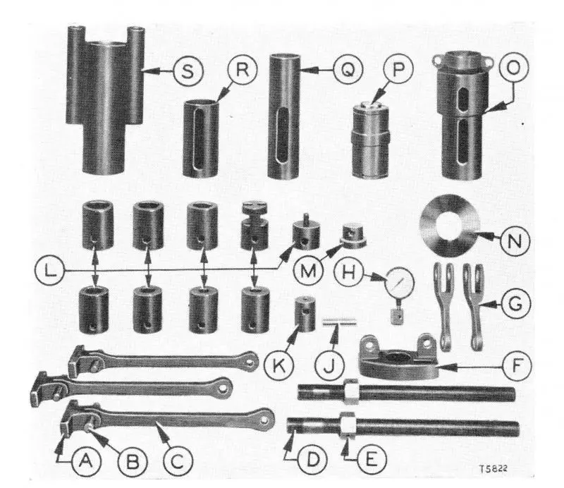
I'll try a few pics. The first is a pic of the spacer, itemised as "P".
The second pic is the sprocket pulling setup. Sorry about the poor quality, the old pics in these old books don't scan well.
[attachment=26292]Cat tools.jpg[/attachment]
[attachment=26293]Sprocket puller.jpg[/attachment]
Your idea of the plates behind the sprocket will work just fine. Make sure the materials you use are high strength steel (T1 equivalent).
Those presses really lay on the pressure and you don't want weak parts failing and turning into missiles in your shop.
You will also probably need to whack the sprocket with a sledgehammer to make it let go, once you have substantial pressure on the press.
Don't forget to just loosen the sprocket retaining nut and leave about 1/4" gap between nut face and sprocket face to allow the sprocket to pop off, without it flying right off the shaft and across the floor!
The 5F7334 spacer sits against the end of the sprocket driving hub and clear of the sprocket shaft (the dead axle).
The pressure has to be applied to the end of the sprocket hub without any pressure on the dead axle.
Old Magnet and OzDozer. Those photos and info help a lot. I was wondering what spec steel to use. T-1 would enable me to use a thinner piece of plate if I have a clearance problem behind the spokes. Thanks for all the help.
This is for a different sprocket/machine but a little better picture of the set up.
the puller tube can be fabercated from a piece of steel pipe with about a 3/8 or 1/2 wall thickness long enough to clear the end of the dead shaft with a plate or plug on the end of the tube to push on it ,I remember the orginal spacer tub was about 3/8 " thick the main thing you want to remember is that you need to fabercate the tube to slip over the hub threads and bare against the sprocket nut after it is loosened away from the sprocket about a 1/8 or3/16 " away from the sprocket .think the manual says to remove the lock ,and screw the nut back on till it is 1/8 to 3/16 away from the sprocket .The orginal tub was used on different tractors ,so the second spacer was actually used to extend the tube for different applications Tube was larger on one end ,so it could be reversed to use on the bigger tractors
The pull on the sprocket is from the back of sprocket and the hub nut outer face or actually the hub ,not the final drive case
Thanks for the additional picture OM and for the procedure rjh. There's tooling for larger machines with the service press that will probably substitute well here with the fabrication of a spacer or two. Probably much less work than I envisioned.


Our channel highlights machines from the earliest Holt and Best track-type tractors, equipment from the start of Caterpillar in 1925, up to units built in the mid-1960s.
Chapter Fifteen
| Historic Santa Margarita Ranch, 20000 El Camino Real, Santa Margarita, CA 93453, USAChapter Thirty
| Hartley - South AustraliaChapter Two
| Newby Hall, Ripon, Noth Yorkshire, HG4 5AJChapter Two
| Freshfield Farm, Sloop Lane, Scaynes Hill RH17 7NP UK
Antique Caterpillar
Machinery Owners Club
1115 Madison St NE # 1117
Salem, OR 97301
Terms & Privacy
Website developed by
AdCo
"I also joined a year ago. had been on here a couple of times as a non-member and found the info very helpful so I got a one year subscription (not very expensive at all) to try it out. I really like all the resources on here so I just got a three year. I think its a very small price for what you can get out of this site."
-Jason N